Infiniti FX35, FX50 (S51). Manual — part 657

P0101, P010B MAF SENSOR
EC-169
< DTC/CIRCUIT DIAGNOSIS >
[VQ35HR]
C
D
E
F
G
H
I
J
K
L
M
A
EC
N
P
O
>> GO TO 2.
2.
PERFORM DTC CONFIRMATION PROCEDURE FOR MALFUNCTION A
1.
Start engine and warm it up to normal operating temperature.
2.
Run engine for at least 10 seconds at idle speed.
3.
Check 1st trip DTC.
Is 1st trip DTC detected?
YES
>> Go to
NO-1
>> With CONSULT-III: GO TO 3.
NO-2
>> With GST: GO TO 5.
3.
CHECK MASS AIR FLOW SENSOR FUNCTION
1.
Start engine and warm it up to normal operating temperature.
If engine cannot be started, go to
2.
Select “MAS A/F SE-B1/B2” in “DATA MONITOR” mode with CONSULT-III.
3.
Check the voltage of “MAS A/F SE-B1/B2”.
4.
Increases engine speed to approximately 4,000 rpm.
5.
Monitor the linear voltage rise in response to engine speed
increases.
Is the inspection result normal?
YES
>> GO TO 4.
NO
>> Go to
4.
PERFORM DTC CONFIRMATION PROCEDURE FOR MALFUNCTION B
1.
Maintain the following conditions for at least 5 consecutive seconds.
CAUTION:
Always drive vehicle at a safe speed.
2.
Check 1st trip DTC.
Is 1st trip DTC detected?
YES
>> Go to
NO
>> INSPECTION END
PBIB3457E
ENG SPEED
More than 1,400 rpm
TP SEN 1-B1
More than 1 V
TP SEN 2-B1
More than 1 V
TP SEN 1-B2
More than 1 V
TP SEN 2-B2
More than 1 V
Selector lever
Suitable position
Driving location
Driving vehicle uphill (Increased engine load) will help
maintain the driving conditions required for this test.
EC-170
< DTC/CIRCUIT DIAGNOSIS >
[VQ35HR]
P0101, P010B MAF SENSOR
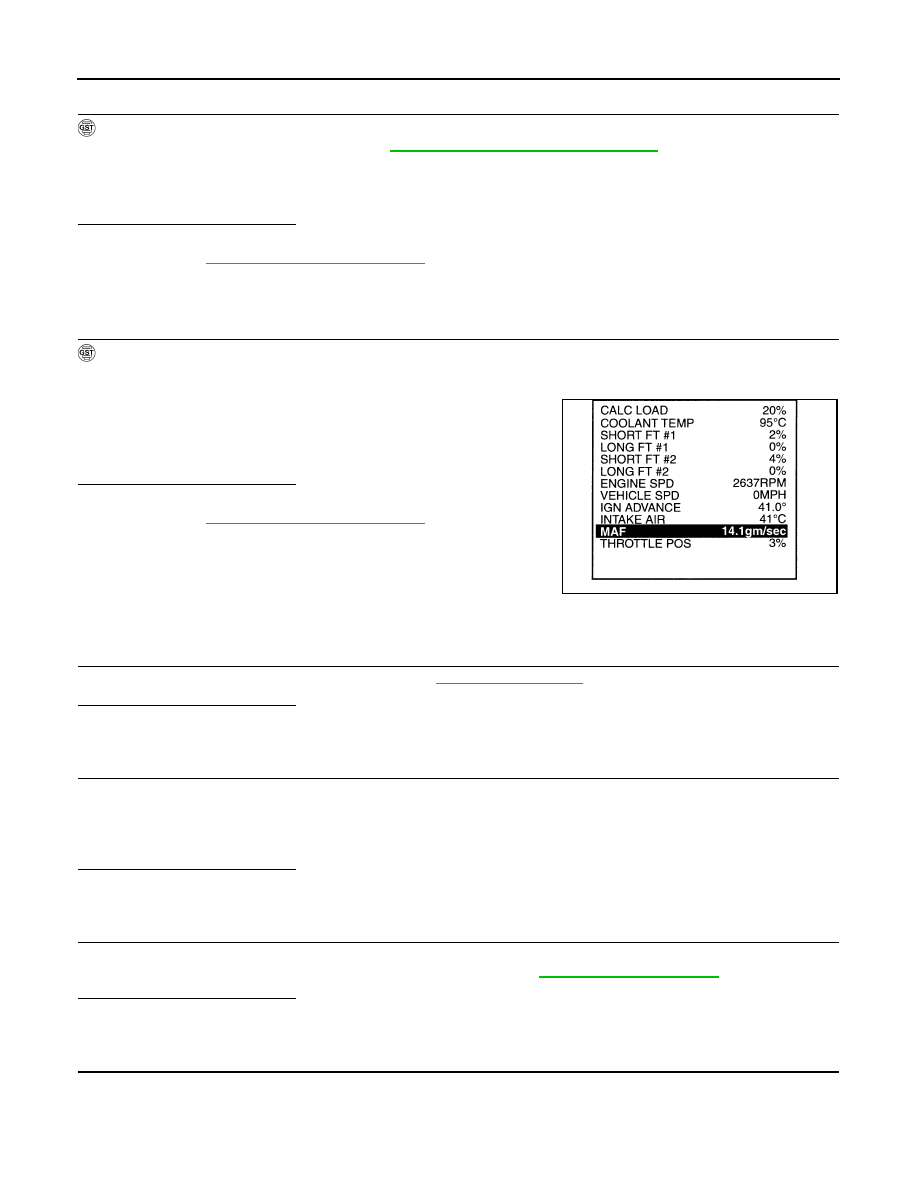
5.
PERFORM COMPONENT FUNCTION CHECK FOR MALFUNCTION B
With GST
Perform component function check. Refer to
EC-170, "Component Function Check"
NOTE:
Use component function check to check the overall function of the mass air flow sensor circuit. During this
check, a 1st trip DTC might not be confirmed.
Is the inspection result normal?
YES
>> INSPECTION END
NO
>> Go to
Component Function Check
INFOID:0000000005236771
1.
PERFORM COMPONENT FUNCTION CHECK FOR MALFUNCTION B
With GST
1.
Start engine and warm it up to normal operating temperature.
2.
Select Service $01 with GST.
3.
Check the mass air flow sensor signal with Service $01.
4.
Check for linear mass air flow sensor signal value rise in
response to increases to approximately 4,000 rpm in engine
speed.
Is the inspection result normal?
YES
>> INSPECTION END
NO
>> Go to
Diagnosis Procedure
INFOID:0000000005236772
1.
INSPECTION START
Confirm the detected malfunction (A or B). Refer to
.
Which malfunction is detected?
A
>> GO TO 3.
B
>> GO TO 2.
2.
CHECK INTAKE SYSTEM
Check the following for connection.
• Air duct
• Vacuum hoses
• Intake air passage between air duct and intake manifold
Is the inspection result normal?
YES
>> GO TO 3.
NO
>> Reconnect the parts.
3.
CHECK GROUND CONNECTION
1.
Turn ignition switch OFF.
2.
Check ground connection M95. Refer to Ground Inspection in
Is the inspection result normal?
YES
>> GO TO 4.
NO
>> Repair or replace ground connection.
4.
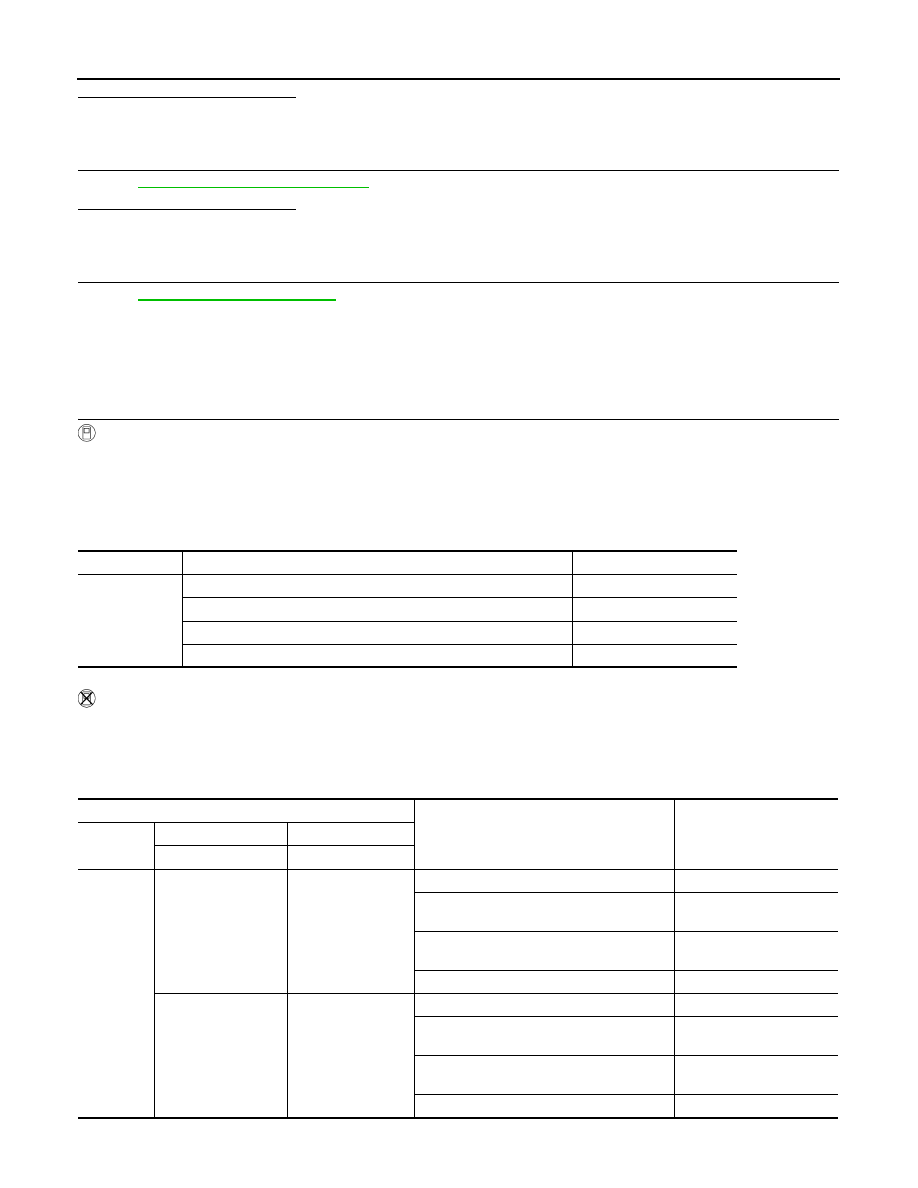
CHECK MASS AIR FLOW (MAF) SENSOR POWER SUPPLY CIRCUIT
1.
Disconnect MAF sensor harness connector.
2.
Turn ignition switch ON.
3.
Check the voltage between MAF sensor harness connector and ground.
SEF534P

P0101, P010B MAF SENSOR
EC-171
< DTC/CIRCUIT DIAGNOSIS >
[VQ35HR]
C
D
E
F
G
H
I
J
K
L
M
A
EC
N
P
O
Is the inspection result normal?
YES
>> GO TO 6.
NO
>> GO TO 5.
5.
DETECT MALFUNCTIONING PART
Check the following.
• Harness connectors E106, M6
• Harness connectors M116, F103
• Harness for open or short between MAF sensor and ECM
• Harness for open or short between MAF sensor and IPDM E/R
>> Repair open circuit, short to ground or short to power in harness or connectors.
6.
CHECK MAF SENSOR GROUND CIRCUIT FOR OPEN AND SHORT
1.
Turn ignition switch OFF.
2.
Disconnect ECM harness connector.
3.
Check the continuity between MAF sensor harness connector and ECM harness connector.
4.
Also check harness for short to ground and short to power.
Is the inspection result normal?
YES
>> GO TO 7.
NO
>> Repair open circuit, short to ground or short to power in harness or connectors.
7.
CHECK MAF SENSOR INPUT SIGNAL CIRCUIT FOR OPEN AND SHORT
1.
Check the continuity between MAF sensor harness connector and ECM harness connector.
2.
Also check harness for short to ground and short to power.
Is the inspection result normal?
YES
>> GO TO 8.
NO
>> Repair open circuit, short to ground or short to power in harness or connectors.
8.
CHECK INTAKE AIR TEMPERATURE SENSOR
Check intake air temperature sensor (bank 1).
Refer to
EC-182, "Component Inspection"
Is the inspection result normal?
YES
>> GO TO 9.
NO
>> Replace MAF sensor (bank 1) (with intake air temperature sensor).
9.
CHECK EVAP CONTROL SYSTEM PRESSURE SENSOR
EC-313, "Component Inspection"
DTC
MAF sensor
Ground
Voltage
Bank
Connector
Terminal
P0101
1
F31
5
Ground
Battery voltage
P010B
2
F42
5
DTC
MAF sensor
ECM
Continuity
Bank
Connector
Terminal
Connector
Terminal
P0101
1
F31
4
F102
68
Existed
P010B
2
F42
4
94
DTC
MAF sensor
ECM
Continuity
Bank
Connector
Terminal
Connector
Terminal
P0101
1
F31
3
F102
77
Existed
P010B
2
F42
3
79
EC-172
< DTC/CIRCUIT DIAGNOSIS >
[VQ35HR]
P0101, P010B MAF SENSOR
Is the inspection result normal?
YES
>> GO TO 10.
NO
>> Replace EVAP control system pressure sensor.
10.
CHECK MAF SENSOR
EC-172, "Component Inspection"
Is the inspection result normal?
YES
>> GO TO 11.
NO
>> Replace malfunctioning MAF sensor.
11.
CHECK INTERMITTENT INCIDENT
GI-36, "Intermittent Incident"
>> INSPECTION END
Component Inspection
INFOID:0000000005236773
1.
CHECK MASS AIR FLOW (MAF) SENSOR-I
With CONSULT-III
1.
Turn ignition switch OFF.
2.
Reconnect all harness connectors disconnected.
3.
Start engine and warm it up to normal operating temperature.
4.
Connect CONSULT-III and select “DATA MONITOR” mode.
5.
Select “MAS A/F SE-B1” and “MAS A/F SE-B2”, and check the indication.
*: Check for linear voltage rise in response to engine being increased to approximately 4,000 rpm.
Without CONSULT-III
1.
Turn ignition switch OFF.
2.
Reconnect all harness connectors disconnected.
3.
Start engine and warm it up to normal operating temperature.
4.
Check the voltage between ECM harness connector terminals under the following conditions.
*: Check for linear voltage rise in response to engine being increased to approximately 4,000 rpm.
Monitor item
Condition
Indication (V)
MAS A/F SE-B1
MAS A/F SE-B2
Ignition switch ON (Engine stopped.)
Approx. 0.4
Idle (Engine is warmed-up to normal operating temperature.)
0.8 - 1.1
2,500 rpm (Engine is warmed-up to normal operating temperature.)
1.4 - 1.7
Idle to approx. 4,000 rpm
0.8 - 1.1 to approx. 2.4*
ECM
Condition
Voltage (V)
Connector
+
–
Terminal
Terminal
F102
77
[MAF sensor (bank 1)
signal]
68
Ignition switch ON (Engine stopped.)
Approx. 0.4
Idle (Engine is warmed-up to normal operat-
ing temperature.)
0.8 - 1.1
2,500 rpm (Engine is warmed-up to normal
operating temperature.)
1.4 - 1.7
Idle to approx. 4,000 rpm
0.8 - 1.1 to approx. 2.4*
79
[MAF sensor (bank 2)
signal]
94
Ignition switch ON (Engine stopped.)
Approx. 0.4
Idle (Engine is warmed-up to normal operat-
ing temperature.)
0.8 - 1.1
2,500 rpm (Engine is warmed-up to normal
operating temperature.)
1.4 - 1.7
Idle to approx. 4,000 rpm
0.8 - 1.1 to approx. 2.4*
Нет комментариевНе стесняйтесь поделиться с нами вашим ценным мнением.
Текст