Infiniti FX35, FX50 (S51). Manual — part 725

P1805 BRAKE SWITCH
EC-441
< DTC/CIRCUIT DIAGNOSIS >
[VQ35HR]
C
D
E
F
G
H
I
J
K
L
M
A
EC
N
P
O
Is the inspection result normal?
YES
>> INSPECTION END
NO
>> Replace stop lamp switch.
Terminals
Condition
Continuity
1 and 2
Brake pedal
Fully released
Not existed
Slightly depressed
Existed
EC-442
< DTC/CIRCUIT DIAGNOSIS >
[VQ35HR]
P2122, P2123 APP SENSOR
P2122, P2123 APP SENSOR
Description
INFOID:0000000005237051
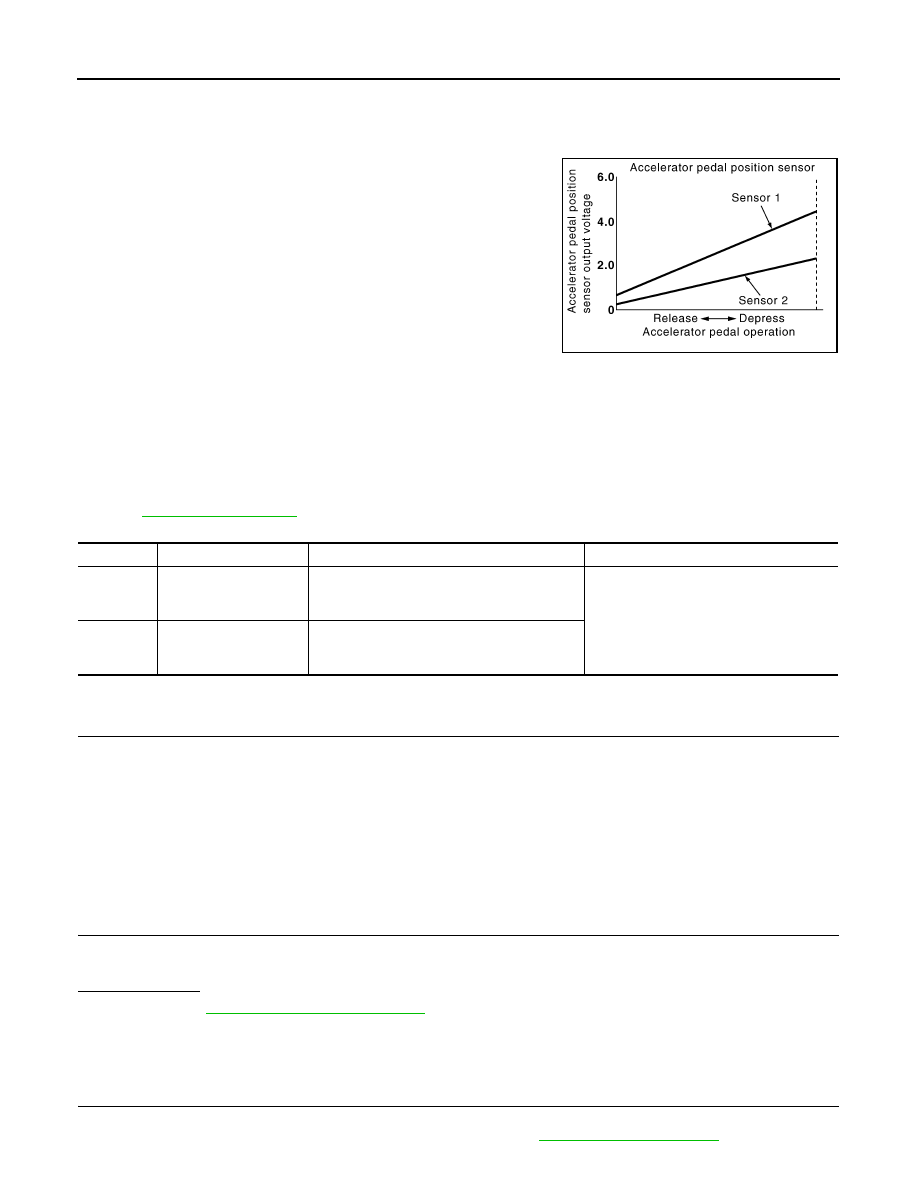
The accelerator pedal position sensor is installed on the upper end
of the accelerator pedal assembly. The sensor detects the accelera-
tor position and sends a signal to the ECM.
Accelerator pedal position sensor has two sensors. These sensors
are a kind of potentiometer which transform the accelerator pedal
position into output voltage, and emit the voltage signal to the ECM.
In addition, these sensors detect the opening and closing speed of
the accelerator pedal and sends voltage signals to the ECM. The
ECM judges the current opening angle of the accelerator pedal from
these signals and controls the throttle control motor based on these
signals.
Idle position of the accelerator pedal is determined by the ECM
receiving the signal from the accelerator pedal position sensor. The ECM uses this signal for engine opera-
tions such as fuel cut.
DTC Logic
INFOID:0000000005237052
DTC DETECTION LOGIC
NOTE:
If DTC P2122 or P2123 is displayed with DTC P0643, first perform the trouble diagnosis for DTC P0643.
Refer to
.
DTC CONFIRMATION PROCEDURE
1.
PRECONDITIONING
If DTC Confirmation Procedure has been previously conducted, always perform the following procedure
before conducting the next test.
1.
Turn ignition switch OFF and wait at least 10 seconds.
2.
Turn ignition switch ON.
3.
Turn ignition switch OFF and wait at least 10 seconds.
TESTING CONDITION:
Before performing the following procedure, confirm that battery voltage is more than 10 V at idle.
>> GO TO 2.
2.
PERFORM DTC CONFIRMATION PROCEDURE
1.
Start engine and let it idle for 1 second.
2.
Check DTC.
Is DTC detected?
YES
>> Go to
NO
>> INSPECTION END
Diagnosis Procedure
INFOID:0000000005237053
1.
CHECK GROUND CONNECTION
1.
Turn ignition switch OFF.
2.
Check ground connection M95. Refer to Ground Inspection in
PBIB1741E
DTC No.
Trouble diagnosis name
DTC detecting condition
Possible cause
P2122
Accelerator pedal posi-
tion (APP) sensor 1 cir-
cuit low input
An excessively low voltage from the APP sen-
sor 1 is sent to ECM.
• Harness or connectors
(APP sensor 1 circuit is open or shorted.)
• Accelerator pedal position sensor
(APP sensor 1)
P2123
Accelerator pedal posi-
tion (APP) sensor 1 cir-
cuit high input
An excessively high voltage from the APP sen-
sor 1 is sent to ECM.

P2122, P2123 APP SENSOR
EC-443
< DTC/CIRCUIT DIAGNOSIS >
[VQ35HR]
C
D
E
F
G
H
I
J
K
L
M
A
EC
N
P
O
Is the inspection result normal?
YES
>> GO TO 2.
NO
>> Repair or replace ground connection.
2.
CHECK ACCELERATOR PEDAL POSITION (APP) SENSOR 1 POWER SUPPLY CIRCUIT
1.
Disconnect APP sensor harness connector.
2.
Turn ignition switch ON.
3.
Check the voltage between APP sensor harness connector and ground.
Is the inspection result normal?
YES
>> GO TO 4.
NO
>> GO TO 3.
3.
DETECT MALFUNCTIONING PART
Check the following.
• Harness connectors M6, E106
• Harness for open or short between ECM and APP sensor
>> Repair open circuit, short to ground or short to power in harness or connectors.
4.
CHECK APP SENSOR 1 GROUND CIRCUIT FOR OPEN AND SHORT
1.
Turn ignition switch OFF.
2.
Disconnect ECM harness connector.
3.
Check the continuity between APP sensor harness connector and ECM harness connector.
4.
Also check harness for short to ground and short to power.
Is the inspection result normal?
YES
>> GO TO 6.
NO
>> GO TO 5.
5.
DETECT MALFUNCTIONING PART
Check the following.
• Harness connectors M6, E106
• Harness for open or short between ECM and APP sensor
>> Repair open circuit, short to ground or short to power in harness or connectors.
6.
CHECK APP SENSOR INPUT SIGNAL CIRCUIT FOR OPEN AND SHORT
1.
Check the continuity between APP sensor harness connector and ECM harness connector.
APP sensor
Ground
Voltage (V)
Connector
Terminal
E112
(Without ICC)
5
Ground
Approx. 5
E116
(With ICC)
APP sensor
ECM
Continuity
Connector
Terminal
Connector
Terminal
E112
(Without ICC)
4
M107
100
Existed
E116
(With ICC)
1

EC-444
< DTC/CIRCUIT DIAGNOSIS >
[VQ35HR]
P2122, P2123 APP SENSOR
2.
Also check harness for short to ground and short to power.
Is the inspection result normal?
YES
>> GO TO 8.
NO
>> GO TO 7.
7.
DETECT MALFUNCTIONING PART
Check the following.
• Harness connectors M6, E106
• Harness for open or short between ECM and APP sensor
>> Repair open circuit, short to ground or short to power in harness or connectors.
8.
CHECK APP SENSOR
EC-444, "Component Inspection"
Is the inspection result normal?
YES
>> GO TO 10.
NO
>> GO TO 9.
9.
REPLACE ACCELERATOR PEDAL ASSEMBLY
1.
Replace accelerator pedal assembly.
2.
Go to
EC-445, "Special Repair Requirement"
.
>> INSPECTION END
10.
CHECK INTERMITTENT INCIDENT
GI-36, "Intermittent Incident"
>> INSPECTION END
Component Inspection
INFOID:0000000005237054
1.
CHECK ACCELERATOR PEDAL POSITION (APP) SENSOR
1.
Turn ignition switch OFF.
2.
Reconnect all harness connectors disconnected.
3.
Turn ignition switch ON.
4.
Check the voltage ECM harness connector terminals under the following conditions.
Is the inspection result normal?
YES
>> INSPECTION END
APP sensor
ECM
Continuity
Connector
Terminal
Connector
Terminal
E112
(Without ICC)
3
M107
97
Existed
E116
(With ICC)
4
ECM
Condition
Voltage (V)
Connector
+
–
Terminal
Terminal
M107
97 (APP sensor 1)
100
Accelerator pedal
Fully released
0.45 - 1.0
Fully depressed
4.4 - 4.8
98 (APP sensor 2)
104
Fully released
0.22 - 0.50
Fully depressed
2.1 - 2.5
Нет комментариевНе стесняйтесь поделиться с нами вашим ценным мнением.
Текст