Infiniti FX35, FX50 (S51). Manual — part 425
CCS-520
< ECU DIAGNOSIS INFORMATION >
[LDW & LDP]
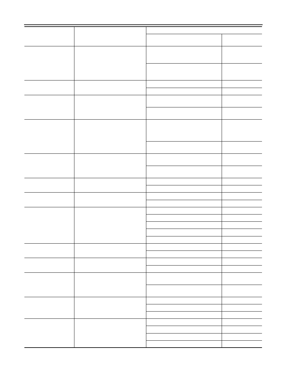
ABS ACTUATOR AND ELECTRIC UNIT (CONTROL UNIT)
HSV [FR-RL]
(Note 2)
VDC switch-over valve
When actuator (switch-over valve) is ac-
tive (“ACTIVE TEST” in “ABS” with CON-
SULT-III)
On
When actuator (switch-over valve) is not
active and actuator relay is active (igni-
tion switch ON)
Off
BST OPER SIG
Booster operation signal
Booster is active
On
Booster is inactive
Off
V/R OUTPUT
(Note 2)
Solenoid valve relay activated
When the solenoid valve relay is active
(When ignition switch OFF)
On
When the solenoid valve relay is not ac-
tive (in the fail-safe mode)
Off
M/R OUTPUT
Actuator motor and motor relay activat-
ed
When the actuator motor and motor relay
are active
(“ACTIVE TEST” in “ABS” with CON-
SULT-III)
On
When the actuator motor and motor relay
are inactive
Off
LDP) APP SEN
(Note 4)
Accelerator pedal position sensor sta-
tus
Accelerator pedal is not depressed (Igni-
tion switch ON)
0 %
Depress accelerator pedal
(Ignition switch ON)
0 - 100 %
LDP) ICC MAIN SW
(Note 4)
ICC main switch
ICC main switch is ON
On
ICC main switch is OFF
Off
LDP) LDP ON SW
(Note 4)
LDP switch
LDP switch is ON
On
LDP switch is OFF
Off
LDP) WIPER SIGNAL
(Note 4)
Front wiper operation
Front wiper is OFF.
Stop
Front wiper stops at fail-safe operation
PRTCT
Front wiper INT is operating.
1low
Front wiper LO is operating.
Low
Front wiper HI is operating.
High
LDP) BRAKE SW
(Note 4)
Brake switch signal status
When brake pedal is not depressed
On
When brake pedal is depressed
Off
LDP) STOP LMP SW
(Note 4)
Stop lamp switch signal status
When brake pedal is depressed
On
When brake pedal is not depressed
Off
LDP) LDW SW
(Note 4)
LDW switch condition
LDW switch is ON
(LDW ON indicator is ON)
On
LDW switch is OFF
(LDW ON indicator is OFF)
Off
LDP) SHIFT POSITION
(Note 4)
Shift position
Shift position is not received
Off
Selector lever position
P/R/N/D
When using manual mode
MM 1st – MM 7th
LDP) TURN SIGNAL
(Note 4)
Turn signal operation
Turn signal is OFF.
Off
Turn signal lamp RH is blinking.
LH
Turn signal lamp LH is blinking.
RH
Turn signal lamp LH and RH are blinking.
LH&RH
Monitor item
Display content
Data monitor
Condition
Reference value in
normal operation
CCS
ABS ACTUATOR AND ELECTRIC UNIT (CONTROL UNIT)
CCS-521
< ECU DIAGNOSIS INFORMATION >
[LDW & LDP]
C
D
E
F
G
H
I
J
K
L
M
B
N
P
A
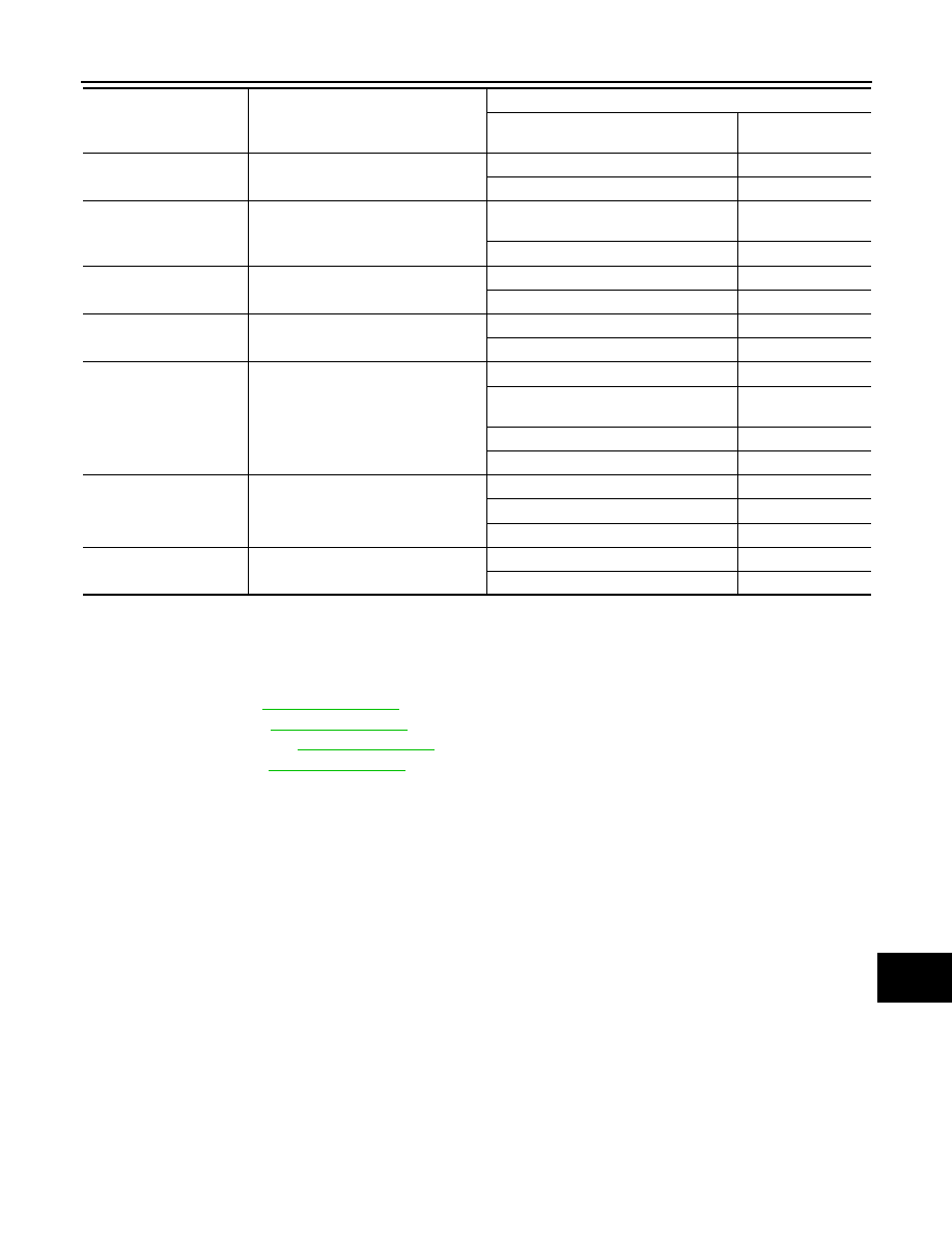
NOTE:
• 1: Confirm tire pressure is normal.
• 2: A brief moment of On/Off condition occurs every 20 seconds after ignition switch turned ON. This is not malfunction because it is an
operation for checking.
• 3: On and off timing for warning lamp and indicator lamp.
.
- Brake warning lamp: Refer to
- VDC OFF indicator lamp: Refer to
- SLIP indicator lamp: Refer to
• 4: With LDP models.
• 5:The item displayed on “SPECIFIC DATA MONITOR” in “Specific Function”.
LDP)YAW ORDER
(Note 4) (Note 5)
Calculated target yaw moment status
LDP is controlling to right side deviation
Negative value
LDP is controlling to left side deviation
Positive value
LDP) WARN REQ
(Note 4) (Note 5)
Lane departure warning request status
Lane departure warning is operating.
(When using LDP)
On
Lane departure warning is not operating.
Off
LDP)WARN CONTROL
(Note 4) (Note 5)
Warning main controller status
When using LDP
On
When using LDW
Off
LDP)REDY SIGNAL
(Note 4) (Note 5)
LDP ready status
LDP control is ready.
On
LDP control is not ready.
Off
LDP)STATUS SIGNAL
(Note 4) (Note 5)
LDP control status
LDP control is standby.
STANDBY
Lane departure warning is operating.
(When using LDP)
WARN
LDP control is stopped.
MASK
LDP control is OFF.
Off
LDP)CAMERA LOST
(Note 4) (Note 5)
Lane marker detected condition
Both side lane markers are detected.
Detect
Deviate side lane marker is lost.
Deviate
Both side lane markers are lost.
Both
LDP)LANE UNCLEAR
(Note 4) (Note 5)
Lane marker condition
Lane marker is unclear.
On
Lane marker is clear.
Off
Monitor item
Display content
Data monitor
Condition
Reference value in
normal operation
CCS-522
< ECU DIAGNOSIS INFORMATION >
[LDW & LDP]
ABS ACTUATOR AND ELECTRIC UNIT (CONTROL UNIT)
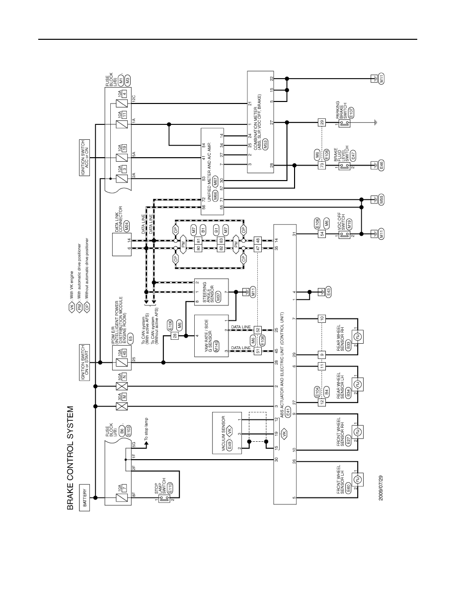
Wiring Diagram - BRAKE CONTROL SYSTEM -
INFOID:0000000005681343
JCFWA0304GB
CCS
ABS ACTUATOR AND ELECTRIC UNIT (CONTROL UNIT)
CCS-523
< ECU DIAGNOSIS INFORMATION >
[LDW & LDP]
C
D
E
F
G
H
I
J
K
L
M
B
N
P
A
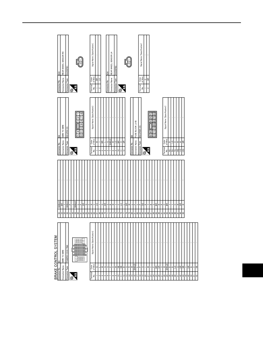
JCFWA0305GB
Нет комментариевНе стесняйтесь поделиться с нами вашим ценным мнением.
Текст