Infiniti FX35, FX50 (S51). Manual — part 1930
C1720, C1721, C1722, C1723 TRANSMITTER
WT-23
< DTC/CIRCUIT DIAGNOSIS >
C
D
F
G
H
I
J
K
L
M
A
B
WT
N
O
P
NO
>> GO TO 4.
2.
CHECK HARNESS BETWEEN LOW TIRE PRESSURE WARNING CONTROL UNIT AND TIRE PRES-
SURE RECEIVER
1.
Turn the ignition switch OFF.
2.
Disconnect low tire pressure warning control unit harness connector and tire pressure receiver harness
connector.
3.
Check the continuity between low tire pressure warning control unit harness connector and tire pressure
receiver harness connector.
CHECK RECEIVER POWER CIRCUIT
CHECK RECEIVER SIGNAL CIRCUIT
CHECK RECEIVER SIGNAL (SENSITIVITY) CIRCUIT
CHECK RECEIVER GROUND CIRCUIT
4.
Check the continuity between low tire pressure warning control unit harness connector and ground.
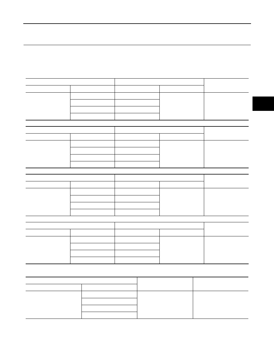
CHECK RECEIVER POWER CIRCUIT
Low tire pressure warning control unit
Tire pressure receiver
Continuity
Connector
Terminal
Connector
Terminal
M96
10
E53 (Front LH)
1
Existed
9
E19 (Front RH)
8
B43 (Rear LH)
7
B251 (Rear RH)
Low tire pressure warning control unit
Tire pressure receiver
Continuity
Connector
Terminal
Connector
Terminal
M96
6
E53 (Front LH)
3
Existed
5
E19 (Front RH)
4
B43 (Rear LH)
3
B251 (Rear RH)
Low tire pressure warning control unit
Tire pressure receiver
Continuity
Connector
Terminal
Connector
Terminal
M96
22
E53 (Front LH)
2
Existed
21
E19 (Front RH)
20
B43 (Rear LH)
19
B251 (Rear RH)
Low tire pressure warning control unit
Tire pressure receiver
Continuity
Connector
Terminal
Connector
Terminal
M96
26
E53 (Front LH)
4
Existed
25
E19 (Front RH)
24
B43 (Rear LH)
23
B251 (Rear RH)
Low tire pressure warning control unit
—
Continuity
Connector
Terminal
M96
10
Ground
Not existed
9
8
7
WT-24
< DTC/CIRCUIT DIAGNOSIS >
C1720, C1721, C1722, C1723 TRANSMITTER
CHECK RECEIVER SIGNAL CIRCUIT
CHECK RECEIVER SIGNAL (SENSITIVITY) CIRCUIT
CHECK RECEIVER GROUND CIRCUIT
Is the inspection result normal?
YES
>> GO TO 3.
NO
>> Repair or replace error-detected parts.
3.
CHECK TIRE PRESSURE RECEIVER
Check the tire pressure receivers. Refer to
.
Is the inspection result normal?
YES
>> GO TO 4.
NO
>> Replace the tire pressure receiver.
4.
CHECK TIRE PRESSURE MONITORING CONTROL SYSTEM
Check the Tire Pressure Monitoring System (TPMS). Refer to
Is the inspection result normal?
YES
>> GO TO 5.
NO
>> Replace the low tire pressure warning control unit.
5.
CHECK TRANSMITTERS
1.
Drive for several minutes at a speed of 40 km/h (25 MPH) or more, then stop the vehicle.
2.
Within 15 minutes, select “DATA MONITOR” of “AIR PRESSURE MONITOR” and display the tire pres-
sure for all wheels.
3.
Check that the tire pressures is the specified value.
Is the inspection result normal?
YES
>> INSPECTION END
NO
>> Replace the transmitter.
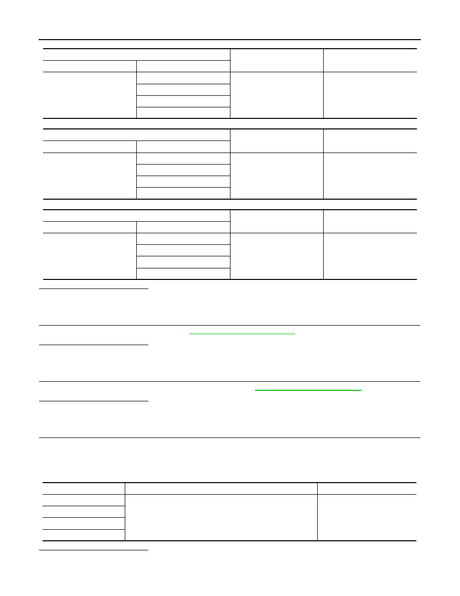
Low tire pressure warning control unit
—
Continuity
Connector
Terminal
M96
6
Ground
Not existed
5
4
3
Low tire pressure warning control unit
—
Continuity
Connector
Terminal
M96
22
Ground
Not existed
21
20
19
Low tire pressure warning control unit
—
Continuity
Connector
Terminal
M96
26
Ground
Not existed
25
24
23
Display Item
Condition
Displayed value
AIR PRESS FL
Drive for several minutes at a speed of 40 km/h (25 MPH) or more,
then stop the vehicle.
Air pressure of tire pressure
AIR PRESS FR
AIR PRESS RR
AIR PRESS RL

C1720, C1721, C1722, C1723 TRANSMITTER
WT-25
< DTC/CIRCUIT DIAGNOSIS >
C
D
F
G
H
I
J
K
L
M
A
B
WT
N
O
P
Special Repair Requirement
INFOID:0000000005549616
1.
CHECK TIRE PRESSURE
Check the tire pressure of all wheels. Refer to
.
Does the tire pressure match the specified value?
YES
>> GO TO 2.
NO
>> Check the road wheels and tires. Adjust the tire pressures to the specified values.
2.
REGISTER TRANSMITTER ID
Perform transmitter ID registration. Refer to
WT-7, "ID REGISTRATION PROCEDURE : Transmitter ID Regis-
.
>> END
WT-26
< DTC/CIRCUIT DIAGNOSIS >
C1728 RECEIVER ID
C1728 RECEIVER ID
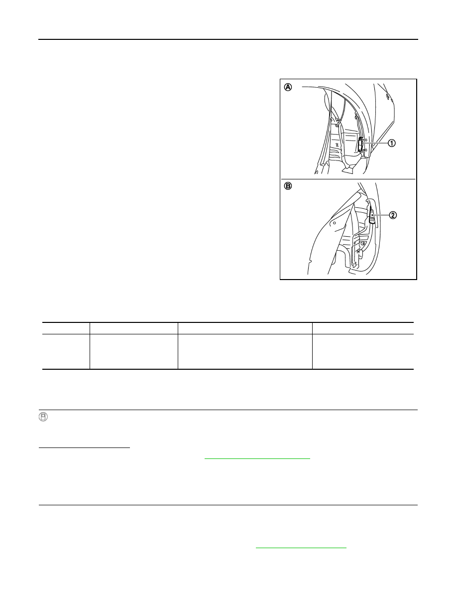
Description
INFOID:0000000005549617
The front (A) tire pressure receiver (1) and rear (B) tire pressure
receiver (2) receive the tire pressure signal by radio waves from the
transmitter at each wheel, and transmit the tire pressure signal to the
low tire pressure warning control unit.
DTC Logic
INFOID:0000000005549618
DTC DETECTION LOGIC
DTC REPRODUCTION PROCEDURE
1.
DTC REPRODUCTION PROCEDURE
With CONSULT-III
1.
Drive for 3 minutes at a speed of 40 km/h (25 MPH) or more, then drive normally for 10 minutes.
2.
Perform “AIR PRESSURE MONITOR” self-diagnosis.
Is DTC “C1728” detected?
YES
>> Perform trouble diagnosis. Refer to
NO
>> INSPECTION END
Diagnosis Procedure
INFOID:0000000005549619
1.
CHECK RECEIVER INPUT SIGNAL
1.
Turn the ignition switch ON.
CAUTION:
Never start engine.
2.
Use an oscilloscope and check the input signal waveform between the low tire pressure warning control
unit harness connector terminals and the ground. Refer to
JSEIA0007ZZ
DTC
Display Item
Malfunction detected condition
Possible causes
C1728
RECEIVER ID NO REG
Receiver ID registration cannot be performed.
• Tire pressure receiver malfunc-
tion
• Low tire pressure warning con-
trol unit malfunction
Нет комментариевНе стесняйтесь поделиться с нами вашим ценным мнением.
Текст