Infiniti FX35, FX50 (S51). Manual — part 1021

EXL-80
< DTC/CIRCUIT DIAGNOSIS >
[XENON TYPE]
TURN SIGNAL LAMP CIRCUIT
TURN SIGNAL LAMP CIRCUIT
Description
INFOID:0000000005244745
BCM performs the high flasher operation (fail-safe) if any bulb or harness of the turn signal lamp circuit is
open.
NOTE:
Turn signal lamp blinks at normal speed when using the hazard warning lamp.
Component Function Check
INFOID:0000000005244746
1.
CHECK TURN SIGNAL LAMP
CONSULT-III ACTIVE TEST
1.
Select "FLASHER" of BCM (FLASHER) active test item.
2.
With operating the test items, check that the turn signal lamp blinks.
Does the turn signal lamp blink?
YES
>> Turn signal lamp circuit is normal.
NO
>> Refer to
.
Diagnosis Procedure
INFOID:0000000005244747
1.
CHECK TURN SIGNAL LAMP BULB
Check the applicable lamp bulb.
Is the bulb normal?
YES
>> GO TO 2.
NO
>> Replace the bulb.
2.
CHECK TURN SIGNAL LAMP OUTPUT VOLTAGE
CONSULT-III ACTIVE TEST
1.
Turn the ignition switch OFF.
2.
Disconnect the front combination lamp connector or the rear combination lamp connector.
3.
Turn the ignition switch ON.
4.
Select "FLASHER" of BCM (FLASHER) active test item.
5.
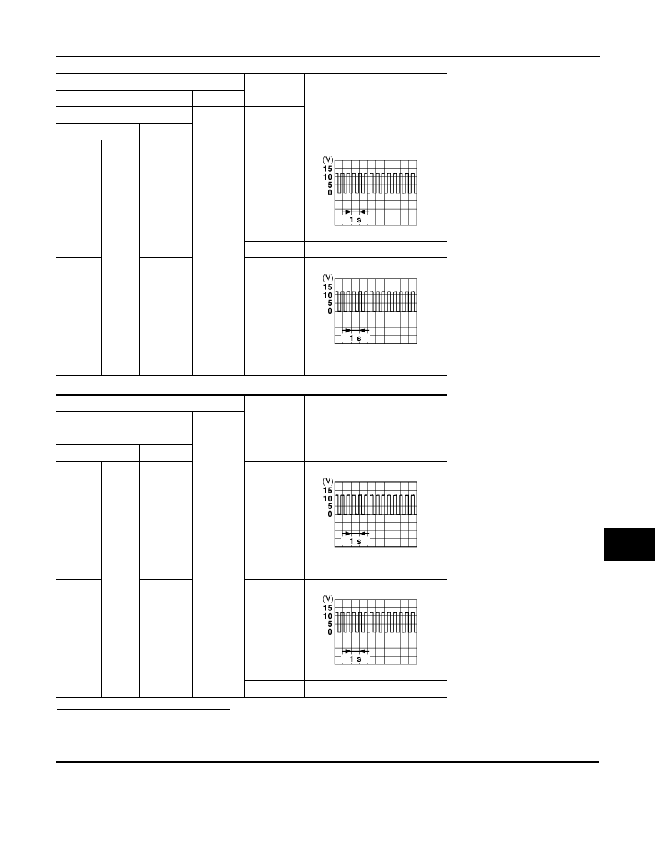
With operating the turn signal switch, check the voltage between the BCM harness connector and the
ground.
LH
: Turn signal lamp LH blinking
RH
: Turn signal lamp RH blinking
Off
: The turn signal lamp OFF
TURN SIGNAL LAMP CIRCUIT
EXL-81
< DTC/CIRCUIT DIAGNOSIS >
[XENON TYPE]
C
D
E
F
G
H
I
J
K
M
A
B
EXL
N
O
P
Front
Rear
Is the measurement value normal?
YES
>> GO TO 3.
NO
>> Replace BCM.
3.
CHECK TURN SIGNAL LAMP OPEN CIRCUIT
1.
Turn the ignition switch OFF.
2.
Disconnect BCM connector.
3.
Check the continuity between the BCM harness connector and the front combination lamp or the rear
combination lamp harness connector.
Terminals
Test item
Voltage (Approx.)
(+)
(
−
)
BCM
Ground
FLASHER
Connector
Terminal
RH
M119
17
RH
Off
0 V
LH
18
LH
Off
0 V
Terminals
Test item
Voltage (Approx.)
(+)
(
−
)
BCM
Ground
FLASHER
Connector
Terminal
RH
M120
20
RH
Off
0 V
LH
25
LH
Off
0 V
PKID0926E
PKID0926E
PKID0926E
PKID0926E

EXL-82
< DTC/CIRCUIT DIAGNOSIS >
[XENON TYPE]
TURN SIGNAL LAMP CIRCUIT
Front turn signal lamp
Rear turn signal lamp
Does continuity exist?
YES
>> GO TO 4.
NO
>> Repair the harnesses or connectors.
4.
CHECK TURN SIGNAL LAMP SHORT CIRCUIT
Check continuity between the BCM harness connector and the ground.
Front
Rear
Does continuity exist?
YES
>> Repair the harnesses or connectors.
NO
>> GO TO 5.
5.
CHECK TURN SIGNAL LAMP GROUND OPEN CIRCUIT
Check the continuity between the BCM harness connector and the front combination lamp or the rear combi-
nation lamp and the ground.
Front turn signal lamp
Rear turn signal lamp
Does continuity exist?
YES
>> Replace the front combination lamp or the rear combination lamp.
NO
>> Repair the harnesses or connectors.
BCM
Front combination lamp
Continuity
Connector
Terminal
Connector
Terminal
RH
M119
17
E28
2
Existed
LH
18
E58
2
BCM
Rear combination lamp
Continuity
Connector
Terminal
Connector
Terminal
RH
M120
20
B232
3
Existed
LH
25
B60
3
BCM
Ground
Continuity
Connector
Terminal
RH
M119
17
Not existed
LH
18
BCM
Ground
Continuity
Connector
Terminal
RH
M120
20
Not existed
LH
25
Front combination lamp
Ground
Continuity
Connector
Terminal
RH
E28
3
Existed
LH
E58
3
Rear combination lamp
Ground
Continuity
Connector
Terminal
RH
B232
4
Existed
LH
B60
4
OPTICAL SENSOR
EXL-83
< DTC/CIRCUIT DIAGNOSIS >
[XENON TYPE]
C
D
E
F
G
H
I
J
K
M
A
B
EXL
N
O
P
OPTICAL SENSOR
Description
INFOID:0000000005244748
Optical sensor converts the outside brightness (lux) to voltage and transmits the optical sensor signal to BCM.
Component Function Check
INFOID:0000000005244749
1.
CHECK OPTICAL SENSOR SIGNAL BY CONSULT-III
CONSULT-III DATA MONITOR
1.
Turn the ignition switch ON.
2.
Select "OPTICAL SENSOR" of BCM (HEADLAMP) data monitor item.
3.
Turn the lighting switch AUTO.
4.
With the optical sensor illuminating, check the monitor status.
*: Illuminates the optical sensor. The value may be less than the standard value if brightness is weak.
Is the item status normal?
YES
>> Optical sensor is normal.
NO
>> Refer to
.
Diagnosis Procedure
INFOID:0000000005244750
1.
CHECK OPTICAL SENSOR POWER SUPPLY INPUT
1.
Turn the ignition switch ON.
2.
Turn the lighting switch AUTO.
3.
Check the voltage between the optical sensor harness connector and the ground.
Is the measurement value normal?
YES
>> GO TO 2.
NO
>> GO TO 4.
2.
CHECK OPTICAL SENSOR GROUND INPUT
Check the voltage between the optical sensor harness connector and the ground.
Is the measurement value normal?
YES
>> GO TO 3.
NO
>> GO TO 6.
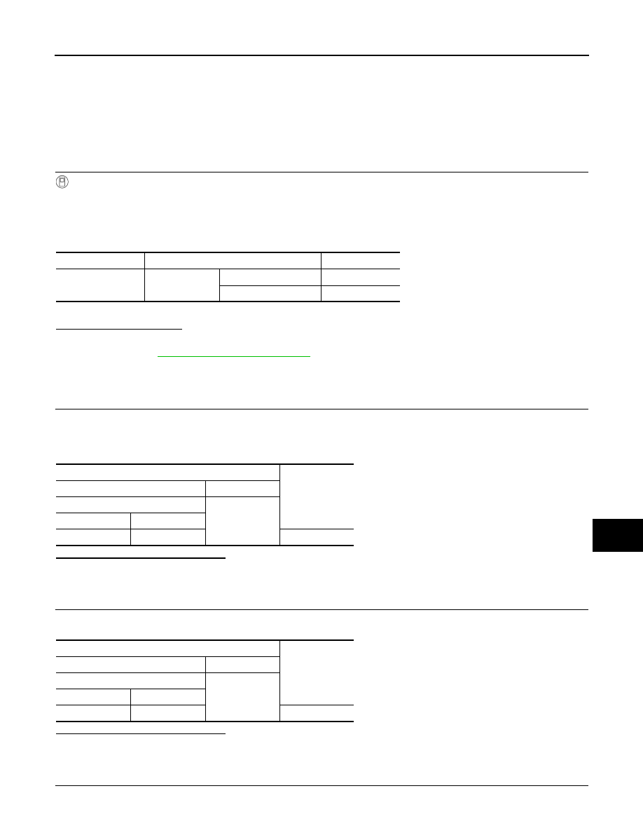
3.
CHECK OPTICAL SENSOR SIGNAL OUTPUT
Monitor item
Condition
Voltage (Approx.)
OPTICAL SENSOR
Optical sensor
When illuminating
3.1 V or more *
When shutting off light
0.6 V or less
Terminals
Voltage
(Approx.)
(+)
(
−
)
Optical sensor
Ground
Connector
Terminal
M94
1
5 V
Terminals
Voltage
(Approx.)
(+)
(
−
)
Optical sensor
Ground
Connector
Terminal
M94
3
0 V
Нет комментариевНе стесняйтесь поделиться с нами вашим ценным мнением.
Текст