Infiniti FX35, FX50 (S51). Manual — part 1614
C1D18 IGN POWER SUPPLY
SCS-41
< DTC/CIRCUIT DIAGNOSIS >
C
D
F
G
H
I
J
K
L
M
A
B
SCS
N
O
P
C1D18 IGN POWER SUPPLY
Description
INFOID:0000000005588955
Power supply for E-SUS control unit.
DTC Logic
INFOID:0000000005588956
DTC DETECTION LOGIC
DTC REPRODUCTION PROCEDURE
1.
DTC REPRODUCTION PROCEDURE
With CONSULT-III
1.
Turn the ignition switch OFF to ON.
2.
Perform “E-SUS” self-diagnosis.
Is DTC “C1D18” detected?
YES
>> Proceed to diagnosis procedure. Refer to
.
NO
>> INSPECTION END
Diagnosis Procedure
INFOID:0000000005588957
1.
CHECK E-SUS CONTROL UNIT GROUND
1.
Turn the ignition switch OFF.
2.
Disconnect the E-SUS control unit harness connector.
3.
Check the continuity between the E-SUS control unit harness connector and ground.
Is the inspection result normal?
YES
>> GO TO 2.
NO
>> Repair or replace the malfunctioning harness or connector.
2.
CHECK E-SUS CONTROL UNIT POWER SUPPLY CIRCUIT
1.
Turn the ignition switch ON.
CAUTION:
Never start the engine.
2.
Check the voltage between the E-SUS control unit harness connector and ground.
Is the measured value “9.0 V” or less?
YES
>>
Check the following items, and repair or replace the malfunctioning parts.
• Open circuit in 10 A fuse (#16)
- Short circuit between the 10 A fuse (#16) connector and E-SUS control unit harness connector
terminal 1, 17
• Battery or ignition switch
NO
>> GO TO 3.
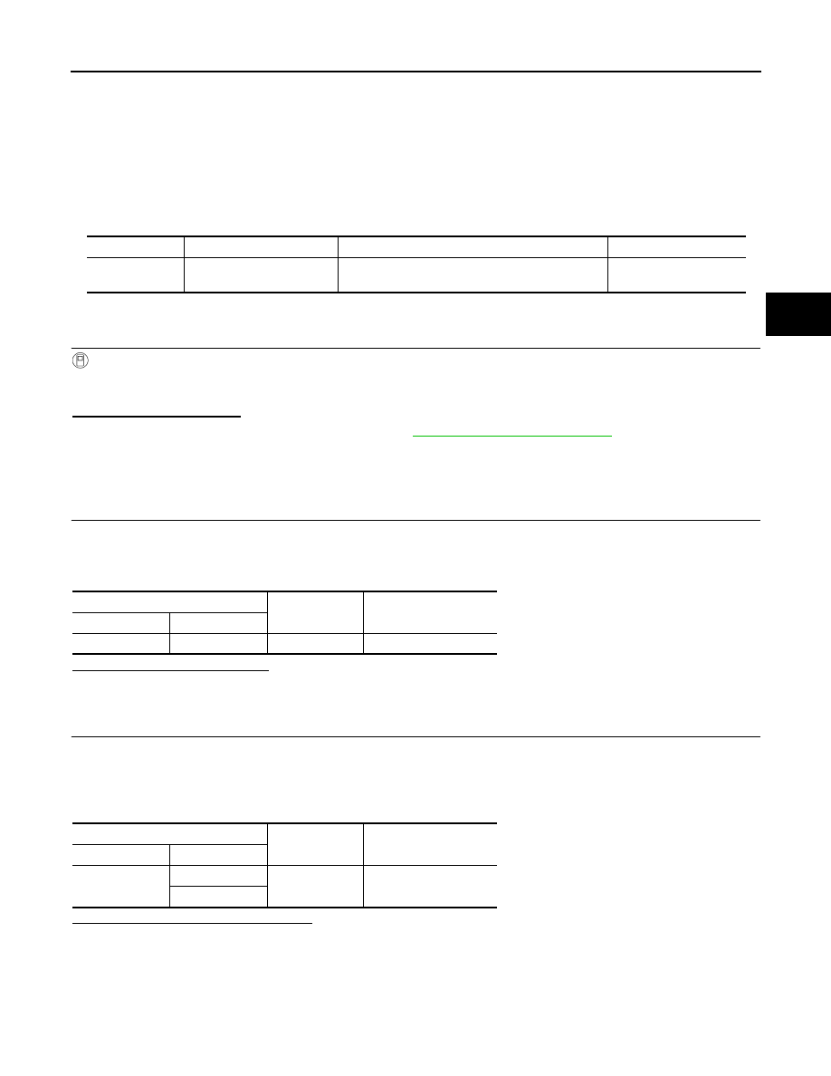
DTC
Display Item
Malfunction detected condition
Possible causes
C1D18
IGN VOLT
A malfunction is detected in the IGN supply voltage
to E-SUS control unit.
• Harness or connector
• E-SUS control unit
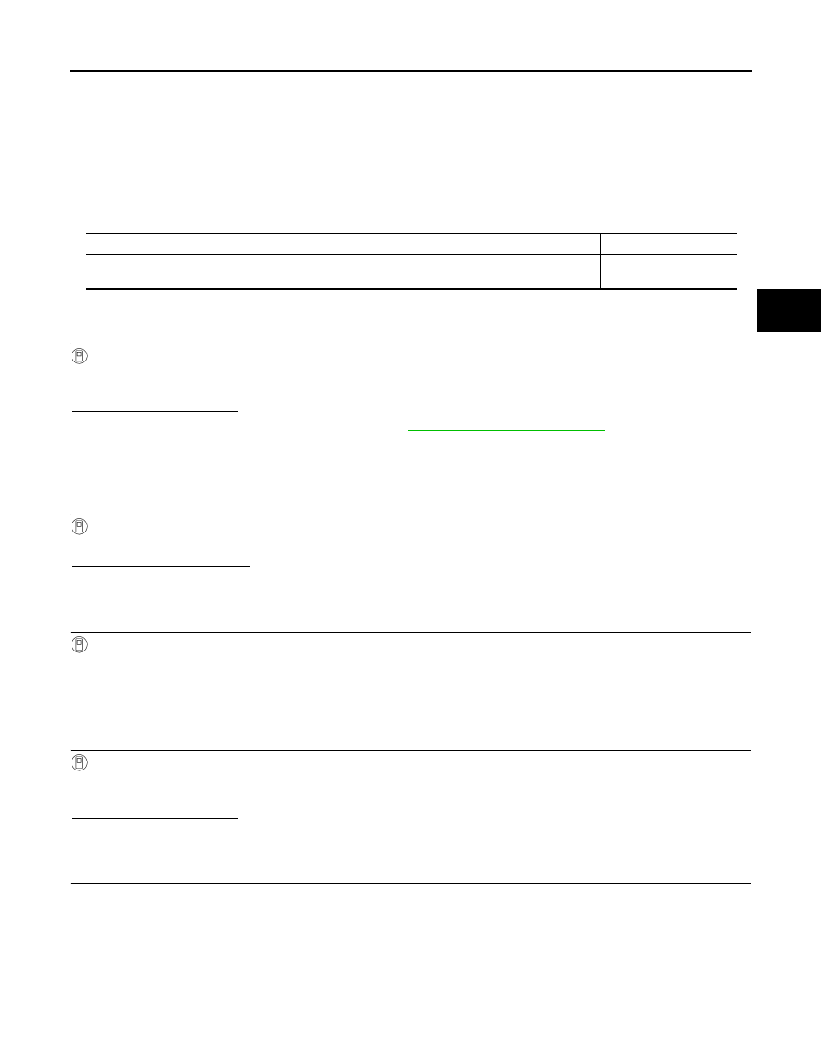
E-SUS control unit
—
Continuity
Connector
Terminal
B38
18, 19
Ground
Existed
E-SUS control unit
—
Voltage
Connector
Terminal
B38
1
Ground
Battery voltage
17

SCS-42
< DTC/CIRCUIT DIAGNOSIS >
C1D18 IGN POWER SUPPLY
3.
CHECK TERMINAL
Check that there is no malfunction in the pin terminals and connection of the E-SUS control unit harness con-
nector.
Is the inspection result normal?
YES
>> GO TO 4.
NO
>> Repair or replace the malfunctioning parts.
4.
CHECK E-SUS CONTROL UNIT SIGNAL
With CONSULT-III
1.
Connect the E-SUS control unit harness connector.
2.
Start the engine.
CAUTION:
Always hold the vehicle stopped.
3.
Select “DATA MONITOR” of “E-SUS”.
4.
Check the value of “IGN” on “DATA MONITOR” screen.
Is the value in “DATA MONITOR” “16 V” or more?
YES
>> Perform the diagnosis by symptom for the charging system. Refer to
.
NO
C1D23 E-SUS CONTROL UNIT
SCS-43
< DTC/CIRCUIT DIAGNOSIS >
C
D
F
G
H
I
J
K
L
M
A
B
SCS
N
O
P
C1D23 E-SUS CONTROL UNIT
Description
INFOID:0000000005588958
Performs good/no good judgment of the E-SUS control unit reprogramming.
DTC Logic
INFOID:0000000005588959
DTC DETECTION LOGIC
DTC REPRODUCTION PROCEDURE
1.
DTC REPRODUCTION PROCEDURE
With CONSULT-III
1.
Turn the ignition switch OFF to ON.
2.
Perform “E-SUS” self-diagnosis.
Is DTC “C1D23” detected?
YES
>> Proceed to diagnosis procedure. Refer to
.
NO
>> INSPECTION END
Diagnosis Procedure
INFOID:0000000005588960
1.
PERFORM E-SUS CONTROL UNIT REPROGRAMMING
With CONSULT-III
Reprogram E-SUS control unit.
Is it completed successfully?
YES
>> GO TO 2.
NO
>> GO TO 3.
2.
PERFORM SELF-DIAGNOSIS
With CONSULT-III
Perform “E-SUS” self-diagnosis.
Is DTC “C1D23” detected?
YES
>> GO TO 3.
NO
>> INSPECTION END
3.
PERFORM E-SUS CONTROL UNIT REPROGRAMMING AGAIN
With CONSULT-III
1.
Reprogram E-SUS control unit.
2.
Perform “E-SUS” self-diagnosis.
Is DTC “C1D23” detected?
YES
>> Replace E-SUS control unit. Refer to
NO
>> GO TO 4.
4.
ERASE ERROR RECORD
Erase the memory of E-SUS control unit self-diagnosis result (history).
>> End
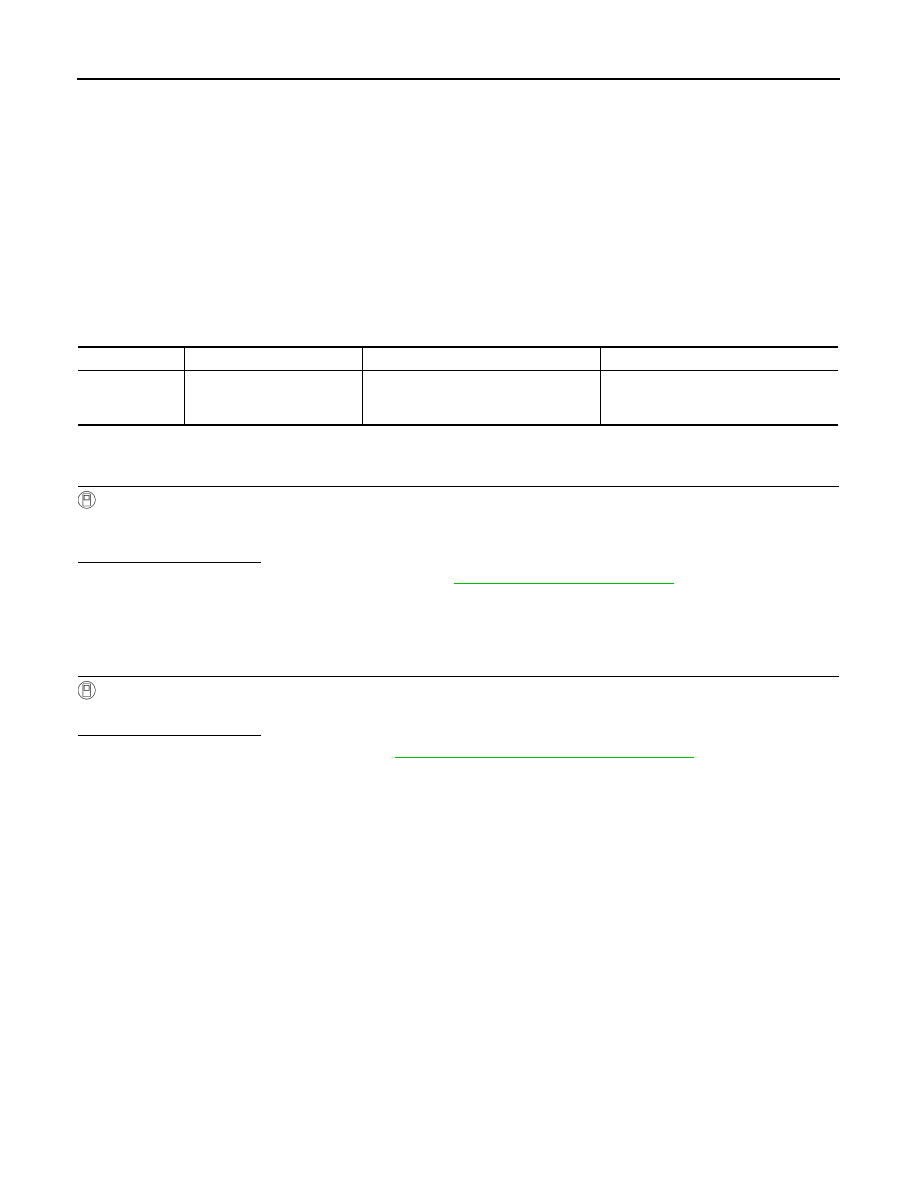
DTC
Display Item
Malfunction detected condition
Possible causes
C1D23
C/U REPRO ERROR
A malfunction is detected at E-SUS control unit re-
programming.
E-SUS control unit
SCS-44
< DTC/CIRCUIT DIAGNOSIS >
U1000 CAN COMM CIRCUIT
U1000 CAN COMM CIRCUIT
Description
INFOID:0000000005588961
CAN (Controller Area Network) is a serial communication line for real time application. It is an on-vehicle mul-
tiplex communication line with high data communication speed and excellent error detectability. Many elec-
tronic control units are equipped onto a vehicle, and each control unit shares information and links with other
control units during operation (not independent). In CAN communication, control units are connected with 2
communication lines (CAN-H line, CAN-L line) allowing a high rate of information communication with less wir-
ing. Each control unit communicates data but selectively reads required data only.
DTC Logic
INFOID:0000000005588962
DTC DETECTION LOGIC
DTC CONFIRMATION PROCEDURE
1.
DTC REPRODUCTION PROCEDURE
With CONSULT-III
1.
Turn the ignition switch OFF to ON.
2.
Perform “E-SUS” self-diagnosis.
Is DTC “U1000” detected?
YES
>> Proceed to diagnosis procedure. Refer to
.
NO
>> INSPECTION END
Diagnosis Procedure
INFOID:0000000005588963
1.
PERFORM SELF-DIAGNOSIS
With CONSULT-III
Perform “E-SUS” self-diagnosis.
Is DTC “U1000” detected?
YES
>> CAN specification chart. Refer to
LAN-29, "CAN System Specification Chart"
NO
>> INSPECTION END
DTC
Display item
Malfunction detected condition
Possible cause
U1000
CAN COMM CIRCUIT
E-SUS control unit is not communicate
CAN communication signal for 2 sec-
onds or more.
• CAN communication error
• Malfunction of E-SUS control unit
Нет комментариевНе стесняйтесь поделиться с нами вашим ценным мнением.
Текст