Infiniti FX35, FX50 (S51). Manual — part 46
ADP-176
< ECU DIAGNOSIS INFORMATION >
BCM (BODY CONTROL MODULE)
80
(GR)
Ground
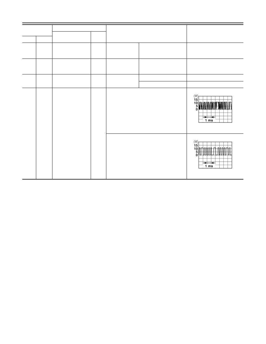
NATS antenna amp.
Input/
Output
During waiting
Ignition switch is pressed
while inserting the Intelli-
gent Key into the key slot.
Just after pressing ignition
switch. Pointer of tester should
move.
81
(W)
Ground
NATS antenna amp.
Input/
Output
During waiting
Ignition switch is pressed
while inserting the Intelli-
gent Key into the key slot.
Just after pressing ignition
switch. Pointer of tester should
move.
82
(P)
Ground
Ignition relay [Fuse
block (J/B)] control
Output
Ignition switch
OFF or ACC
0 V
ON
12 V
83
(GR)
Ground
Remote keyless entry
receiver communica-
tion
Input/
Output
During waiting
When operating either button on the Intelligent
Key
Terminal No.
(Wire color)
Description
Condition
Value
(Approx.)
Signal name
Input/
Output
+
–
JMKIA0064GB
JMKIA0065GB
BCM (BODY CONTROL MODULE)
ADP-177
< ECU DIAGNOSIS INFORMATION >
C
D
E
F
G
H
I
K
L
M
A
B
ADP
N
O
P
87
(BR)
Ground
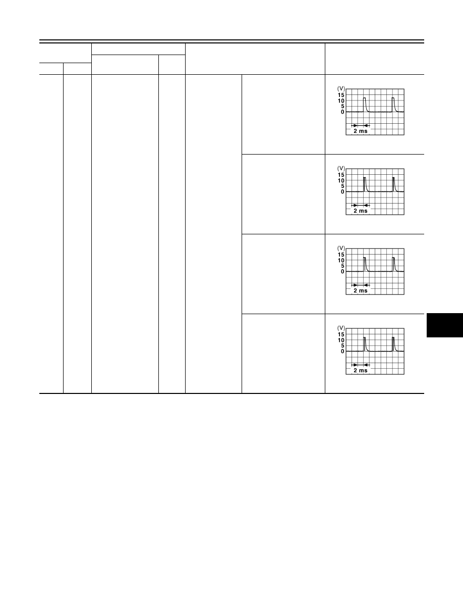
Combination switch
INPUT 5
Input
Combination
switch
All switches OFF
(Wiper intermittent dial 4)
1.4 V
Front fog lamp switch ON
(Wiper intermittent dial 4)
1.3 V
Rear wiper switch ON
(Wiper intermittent dial 4)
1.3 V
Any of the conditions below
with all switches OFF
• Wiper intermittent dial 1
• Wiper intermittent dial 2
• Wiper intermittent dial 6
• Wiper intermittent dial 7
1.3 V
Terminal No.
(Wire color)
Description
Condition
Value
(Approx.)
Signal name
Input/
Output
+
–
JPMIA0041GB
JPMIA0037GB
JPMIA0039GB
JPMIA0040GB
ADP-178
< ECU DIAGNOSIS INFORMATION >
BCM (BODY CONTROL MODULE)
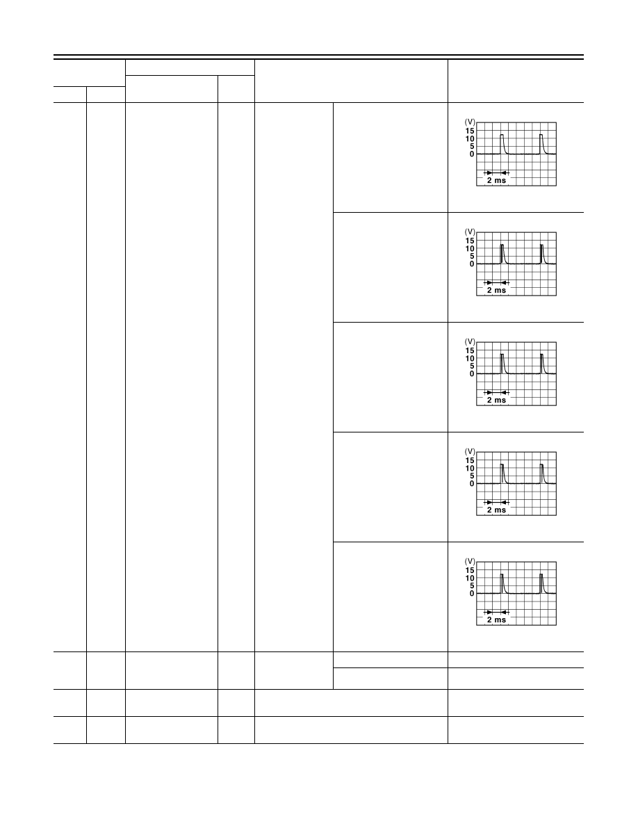
88
(V)
Ground
Combination switch
INPUT 3
Input
Combination
switch
All switches OFF
(Wiper intermittent dial 4)
1.4 V
Lighting switch HI
(Wiper intermittent dial 4)
1.3 V
Lighting switch 2ND
(Wiper intermittent dial 4)
1.3 V
Rear washer switch ON
(Wiper intermittent dial 4)
1.3 V
Any of the conditions below
with all switches OFF
• Wiper intermittent dial 1
• Wiper intermittent dial 2
• Wiper intermittent dial 3
1.3 V
89
(SB)
Ground
Push-button ignition
switch (Push switch)
Input
Push-button igni-
tion switch (Push
switch)
Pressed
0 V
Not pressed
12 V
90
(P)
Ground
CAN-L
Input/
Output
—
—
91
(L)
Ground
CAN-H
Input/
Output
—
—
Terminal No.
(Wire color)
Description
Condition
Value
(Approx.)
Signal name
Input/
Output
+
–
JPMIA0041GB
JPMIA0036GB
JPMIA0037GB
JPMIA0039GB
JPMIA0040GB
BCM (BODY CONTROL MODULE)
ADP-179
< ECU DIAGNOSIS INFORMATION >
C
D
E
F
G
H
I
K
L
M
A
B
ADP
N
O
P
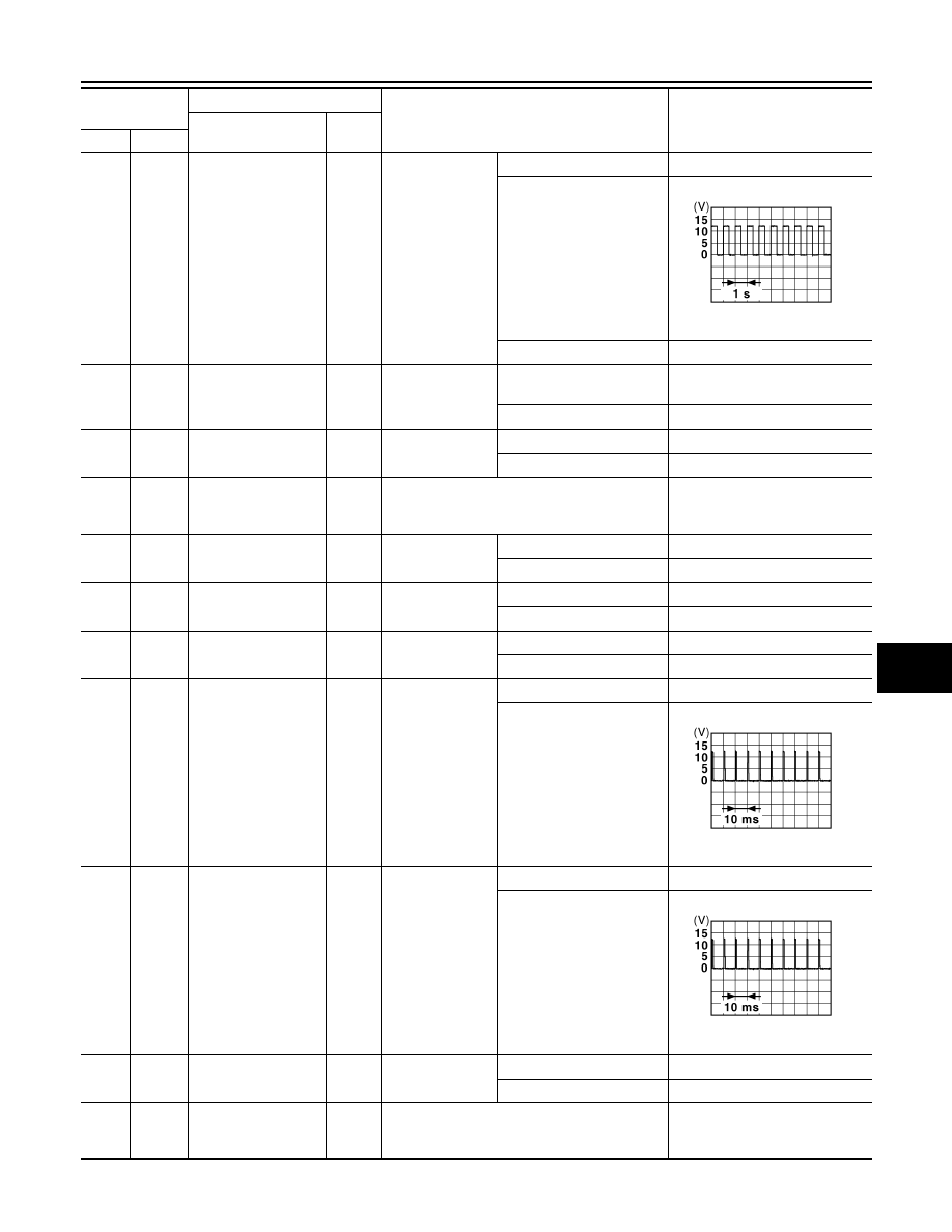
92
(LG)
Ground
Key slot illumination
Output
Key slot illumina-
tion
OFF
12 V
Blinking
6.5 V
ON
0 V
93
(V)
Ground
ON indicator lamp
Output
Ignition switch
OFF (LOCK indicator is not
illuminated)
Battery voltage
ON or ACC
0 V
95
(O)
Ground
ACC relay control
Output
Ignition switch
OFF
0 V
ACC or ON
12 V
96
(GR)
Ground
A/T shift selector (De-
tention switch) power
supply
Output
—
12 V
97
(L)
Ground
Steering lock condi-
tion No. 1
Input
Steering lock
LOCK status
0 V
UNLOCK status
12 V
98
(P)
Ground
Steering lock condi-
tion No. 2
Input
Steering lock
LOCK status
12 V
UNLOCK status
0 V
99
(R)
Ground
Selector lever P posi-
tion switch
Input
Selector lever
P position
0 V
Any position other than P
12 V
100
(G)
Ground
Passenger door re-
quest switch
Input
Passenger door
request switch
ON (Pressed)
0 V
OFF (Not pressed)
1.0 V
101
(SB)
Ground
Driver door request
switch
Input
Driver door re-
quest switch
ON (Pressed)
0 V
OFF (Not pressed)
1.0 V
102
(O)
Ground
Blower fan motor re-
lay control
Output
Ignition switch
OFF or ACC
0 V
ON
12 V
103
(BR)
Ground
Remote keyless entry
receiver power sup-
ply
Output
Ignition switch OFF
12 V
Terminal No.
(Wire color)
Description
Condition
Value
(Approx.)
Signal name
Input/
Output
+
–
JPMIA0015GB
JPMIA0016GB
JPMIA0016GB
Нет комментариевНе стесняйтесь поделиться с нами вашим ценным мнением.
Текст