Infiniti FX35, FX50 (S51). Manual — part 1375
MWI
METER SYSTEM
MWI-19
< SYSTEM DESCRIPTION >
C
D
E
F
G
H
I
J
K
L
M
B
A
O
P
FUEL GAUGE : Component Parts Location
INFOID:0000000005524567
JPNIA1104ZZ
MWI-20
< SYSTEM DESCRIPTION >
METER SYSTEM
FUEL GAUGE : Component Description
INFOID:0000000005524568
ODO/TRIP METER
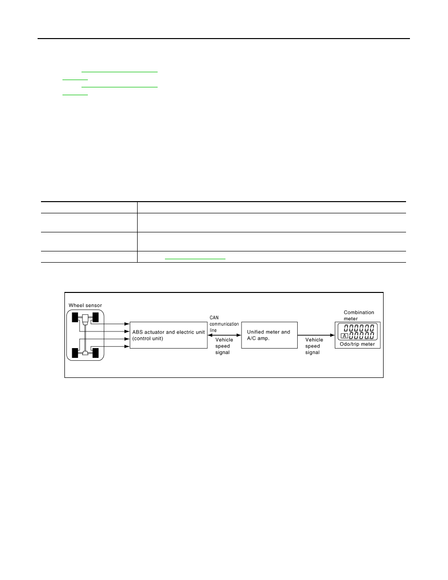
ODO/TRIP METER : System Diagram
INFOID:0000000005524569
ODO/TRIP METER : System Description
INFOID:0000000005524570
• The unified meter and A/C amp. transmits the vehicle speed signal from ABS actuator and electric unit (con-
trol unit) to the combination meter.
• The combination meter calculates the vehicle distance according to the vehicle speed signal. The vehicle
distance is displayed.
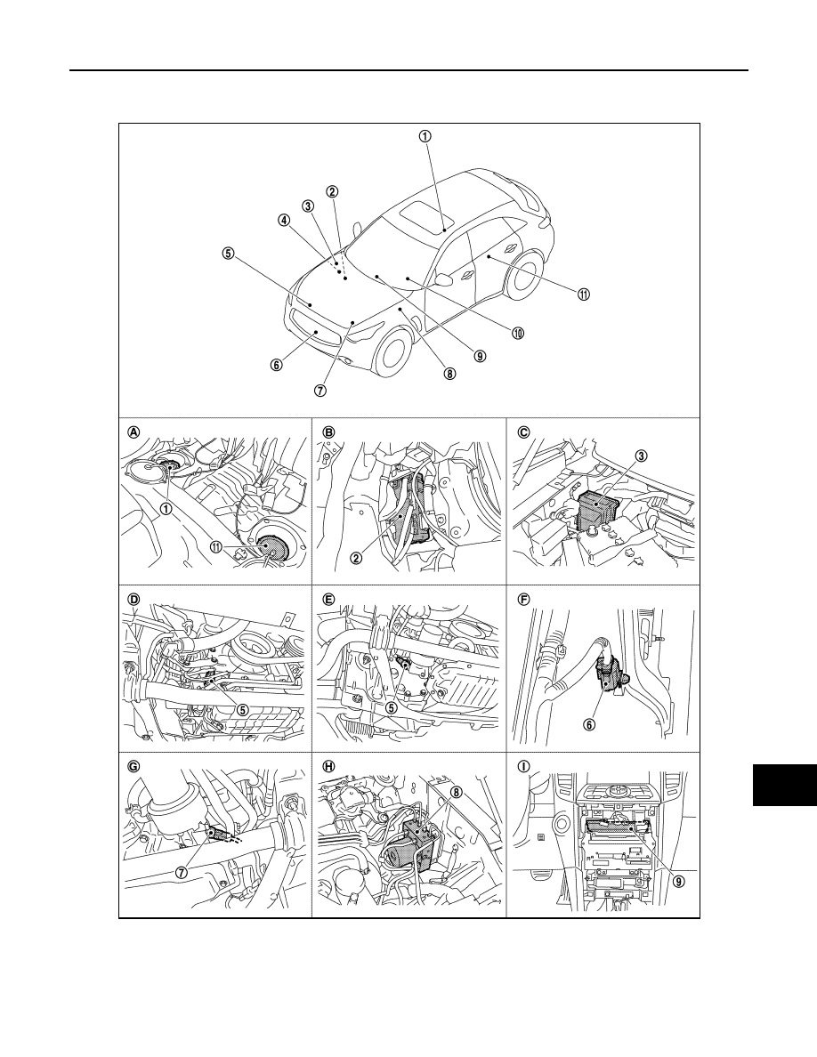
1.
Fuel level sensor unit and fuel pump
(main)
2.
BCM
3.
IPDM E/R
4.
ECM :
(VQ35HR engine models)
ECM :
(VK50VE engine models)
5.
Oil pressure switch (VQ35HR engine
models)
6.
Ambient sensor
7.
Oil pressure switch (VK50VE engine
models)
8.
ABS actuator and electric unit (con-
trol unit)
9.
Unified meter and A/C amp.
10. Combination meter
11.
Fuel level sensor unit (sub)
A.
Rear seat (bottom)
B.
Dash side finisher (passenger side)
C.
Hoodledge cover (RH)
D.
2WD [oil pan (upper) RH side]
E.
AWD [oil filter bracket part (VQ35HR
engine models)]
F.
Condenser (front)
G.
AWD [oil filter bracket part (VK50VE
engine models)]
H.
Hoodledge cover (LH)
I.
Behind cluster lid C
Unit
Description
Combination meter
Indicates the fuel gauge according to the fuel level sensor signal received from the unified meter
and A/C amp. by means of communication line.
Unified meter and A/C amp.
Transmits the fuel level sensor signal from the fuel level sensor unit to the combination meter by
means of communication line.
Fuel level sensor unit
.
JSNIA0022GB

MWI
METER SYSTEM
MWI-21
< SYSTEM DESCRIPTION >
C
D
E
F
G
H
I
J
K
L
M
B
A
O
P
ODO/TRIP METER : Component Parts Location
INFOID:0000000005524571
JPNIA1104ZZ
MWI-22
< SYSTEM DESCRIPTION >
METER SYSTEM
ODO/TRIP METER : Component Description
INFOID:0000000005524572
SHIFT POSITION INDICATOR
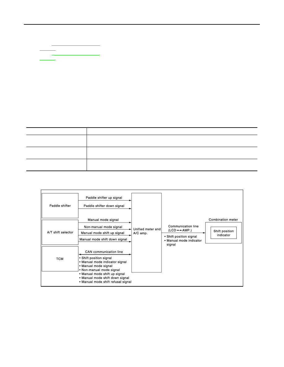
SHIFT POSITION INDICATOR : System Diagram
INFOID:0000000005531172
SHIFT POSITION INDICATOR : System Description
INFOID:0000000005531173
Shift position is displayed in the information display LCD in the combination meter.
MANUAL MODE
When Operated with A/T Shift Selector
• Unified meter and A/C amp. inputs manual mode signal and manual mode shift-up/down signal from A/T
shift selector (manual mode switch), and transmits the signals to TCM with CAN communication line.
• TCM processes manual mode signal and manual mode shift-up/down signal, and transmits manual mode
indicator signal and shift position signal to unified meter and A/C amp. with CAN communication line.
1.
Fuel level sensor unit and fuel pump
(main)
2.
BCM
3.
IPDM E/R
4.
ECM :
(VQ35HR engine models)
ECM :
(VK50VE engine models)
5.
Oil pressure switch (VQ35HR engine
models)
6.
Ambient sensor
7.
Oil pressure switch (VK50VE engine
models)
8.
ABS actuator and electric unit (con-
trol unit)
9.
Unified meter and A/C amp.
10. Combination meter
11.
Fuel level sensor unit (sub)
A.
Rear seat (bottom)
B.
Dash side finisher (passenger side)
C.
Hoodledge cover (RH)
D.
2WD [oil pan (upper) RH side]
E.
AWD [oil filter bracket part (VQ35HR
engine models)]
F.
Condenser (front)
G.
AWD [oil filter bracket part (VK50VE
engine models)]
H.
Hoodledge cover (LH)
I.
Behind cluster lid C
Unit
Description
Combination meter
The combination meter calculates the vehicle distance according to the vehicle speed signal. The
vehicle distance is displayed.
Unified meter and A/C amp.
The unified meter and A/C amp. transmits the vehicle speed signal from ABS actuator and electric
unit (control unit) to the combination meter.
ABS actuator and electric unit
(control unit)
Transmits the vehicle speed signal to the unified meter and A/C amp. with CAN communication
line.
JSNIA2515GB
Нет комментариевНе стесняйтесь поделиться с нами вашим ценным мнением.
Текст