Infiniti FX35, FX50 (S51). Manual — part 1797

STARTER MOTOR
STR-19
< REMOVAL AND INSTALLATION >
C
D
E
F
G
H
I
J
K
L
M
A
STR
N
P
O
Type: S114-927
VQ35HR : Removal and Installation (2WD)
INFOID:0000000005245535
Removal
1.
Disconnect the battery cable from the negative terminal.
2.
Remove engine undercover using power tools.
3.
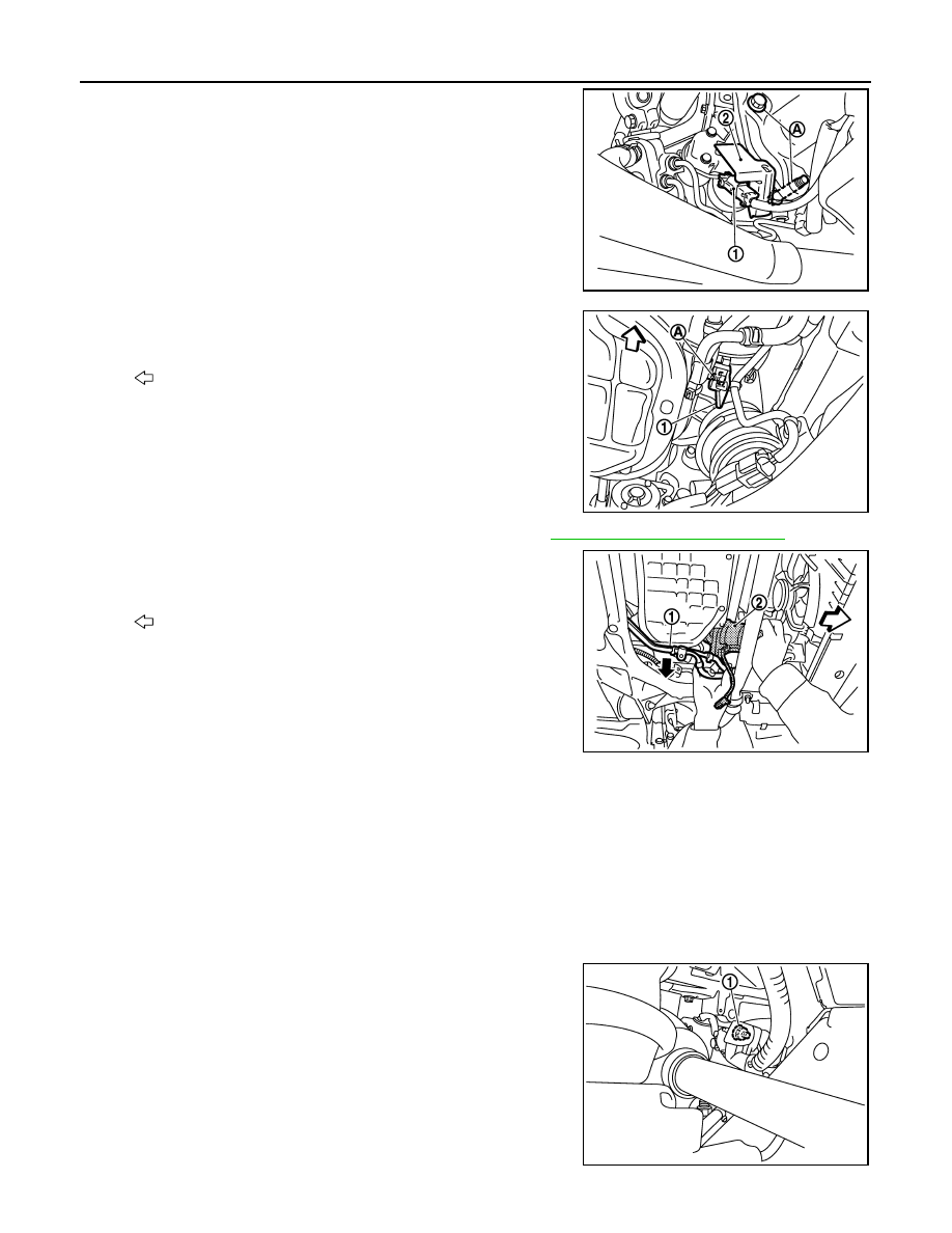
Remove “B” terminal nut (1).
JPBIA0148GB
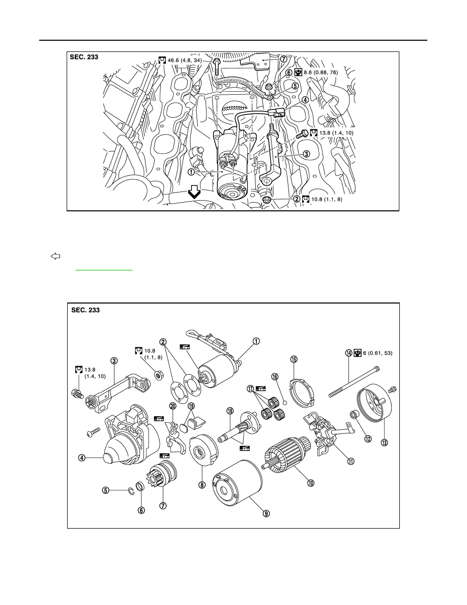
1.
Magnetic switch assembly
2.
Dust cover kit
3.
Shift lever set
4.
Center bracket (A)
5.
Yoke assembly
6.
Armature assembly
7.
Brush holder assembly
8.
Thrust washer
9.
Rear cover assembly
10. Shaft gear assembly
11.
Packing
12. Thrust washer
13. Center bracket (P)
14. E-ring
15. Pinion assembly
16. Pinion stopper
17. Pinion stopper clip
18. Gear case assembly
: High-temperature grease point
Refer to
for symbols not described on the above.
PKIB8802E
STR-20
< REMOVAL AND INSTALLATION >
STARTER MOTOR
4.
Disconnect “S” connector (1).
5.
Remove starter motor mounting bolts (A) and harness bracket
(2), using power tools.
6.
Remove compressor bracket bolts (A).
7.
Remove compressor bracket (1).
8.
Remove A/T fluid cooler tube clip bolts and bracket. Refer to
9.
Move A/T fluid cooler tube (1) downward.
10. Remove starter motor (2) forward from the vehicle.
INSTALLATION
Install in the reverse order of removal.
CAUTION:
Be sure to tighten “B” terminal nut carefully.
VQ35HR : Removal and Installation (AWD)
INFOID:0000000005245536
Removal
1.
Disconnect the battery cable from the negative terminal.
2.
Remove engine undercover, using power tools.
3.
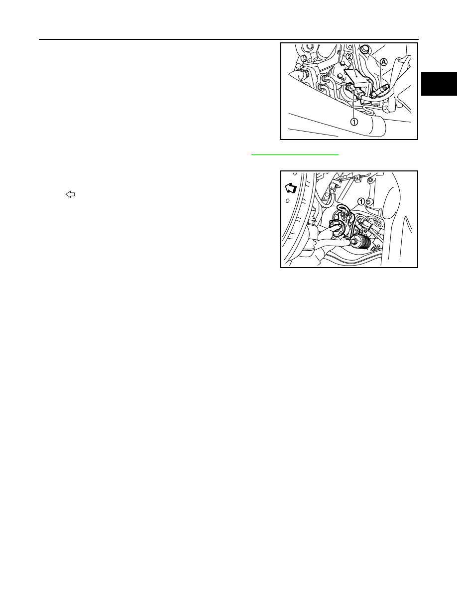
Remove “B” terminal nut (1).
PKIB8803E
: Vehicle front
JSBIA0011ZZ
: Vehicle front
JSBIA0012ZZ
PKIB8802E
STARTER MOTOR
STR-21
< REMOVAL AND INSTALLATION >
C
D
E
F
G
H
I
J
K
L
M
A
STR
N
P
O
4.
Disconnect “S” connector (1).
5.
Remove starter motor mounting bolts (A) and harness bracket
(2), using power tools.
6.
Remove front drive shaft left side housing bolts. Refer to
.
7.
Move a front drive shaft left side forward.
8.
Remove stater motor (1) to left side from the vehicle.
INSTALLATION
Install in the reverse order of removal.
CAUTION:
Be sure to tighten “B” terminal nut carefully.
VQ35HR : Inspection
INFOID:0000000005245537
INSPECTION AFTER DISASSEMBLY
Pinion/Clutch Check
1.
Inspect pinion teeth.
• Replace pinion if teeth are worn or damaged. (Also check condition of ring gear teeth.)
2.
Inspect reduction gear teeth.
• Replace reduction gear if teeth are worn or damaged. (Also check condition of armature shaft gear
teeth.)
3.
Check to see if pinion locks in one direction and rotates smoothly in the opposite direction.
• If it locks or rotates in both directions, or unusual resistance is evident, replace.
VK50VE
VK50VE : Exploded View
INFOID:0000000005245538
REMOVAL
PKIB8803E
: Vehicle front
JSBIA0014ZZ
STR-22
< REMOVAL AND INSTALLATION >
STARTER MOTOR
DISASSEMBLY
Type: M001T30671
1.
Starter motor
2.
“B” terminal extension nut
3.
“B” terminal extension
4.
“S” connector
5.
“B” terminal harness
6.
“B” terminal nut
7.
“S” connector bracket
: Engine front
Refer to
for symbols in the figure.
JPBIA2482GB
JPBIA2426GB
1.
Magnetic switch assembly
2.
Adjusting plate
3.
“B” terminal extension
4.
Gear case assembly
5.
Stopper ring
6.
Stopper
7.
Pinion assembly
8.
Internal gear
9.
Yoke assembly
10. Armature assembly
11.
Brush holder assembly
12. Metal RR
Нет комментариевНе стесняйтесь поделиться с нами вашим ценным мнением.
Текст