Infiniti FX35, FX50 (S51). Manual — part 1292

LAN-110
< ECU DIAGNOSIS INFORMATION >
[CAN GATEWAY]
CAN GATEWAY
DTC Index
INFOID:0000000005241955
NOTE:
• The details of time display are as follows.
- CRNT: A malfunction is detected now
- PAST: A malfunction was detected in the past.
• IGN counter is displayed on FFD (Freeze Frame Data).
- The number is 0 when is detected now
- The number increases like 1
→
2 ··· 38
→
39 after returning to the normal condition whenever IGN OFF
→
ON.
- The number is fixed to 39 until the self-diagnosis results are erased if it is over 39.
Priority
DTC
1
• B2600: CONFIG ERROR
• U1010: CONTROL UNIT(CAN)
2
U1000: CAN COMM CIRCUIT
DTC
Fail-safe
Reference
No DTC is detected.
Further testing may be required.
—
—
U1000: CAN COMM CIRCUIT
—
U1010: CONTROL UNIT(CAN)
—
B2600: CONFIG ERROR
WRONG DATA
—
NOT CONFIGURED
LAN
PRECAUTIONS
LAN-111
< PRECAUTION >
[CAN GATEWAY]
C
D
E
F
G
H
I
J
K
L
B
A
O
P
N
PRECAUTION
PRECAUTIONS
Precaution for Supplemental Restraint System (SRS) "AIR BAG" and "SEAT BELT
PRE-TENSIONER"
INFOID:0000000005241956
The Supplemental Restraint System such as “AIR BAG” and “SEAT BELT PRE-TENSIONER”, used along
with a front seat belt, helps to reduce the risk or severity of injury to the driver and front passenger for certain
types of collision. This system includes seat belt switch inputs and dual stage front air bag modules. The SRS
system uses the seat belt switches to determine the front air bag deployment, and may only deploy one front
air bag, depending on the severity of a collision and whether the front occupants are belted or unbelted.
Information necessary to service the system safely is included in the “SRS AIR BAG” and “SEAT BELT” of this
Service Manual.
WARNING:
• To avoid rendering the SRS inoperative, which could increase the risk of personal injury or death in
the event of a collision which would result in air bag inflation, all maintenance must be performed by
an authorized NISSAN/INFINITI dealer.
• Improper maintenance, including incorrect removal and installation of the SRS, can lead to personal
injury caused by unintentional activation of the system. For removal of Spiral Cable and Air Bag
Module, see the “SRS AIR BAG”.
• Do not use electrical test equipment on any circuit related to the SRS unless instructed to in this
Service Manual. SRS wiring harnesses can be identified by yellow and/or orange harnesses or har-
ness connectors.
PRECAUTIONS WHEN USING POWER TOOLS (AIR OR ELECTRIC) AND HAMMERS
WARNING:
• When working near the Air Bag Diagnosis Sensor Unit or other Air Bag System sensors with the
ignition ON or engine running, DO NOT use air or electric power tools or strike near the sensor(s)
with a hammer. Heavy vibration could activate the sensor(s) and deploy the air bag(s), possibly
causing serious injury.
• When using air or electric power tools or hammers, always switch the ignition OFF, disconnect the
battery, and wait at least 3 minutes before performing any service.
LAN-112
< REMOVAL AND INSTALLATION >
[CAN GATEWAY]
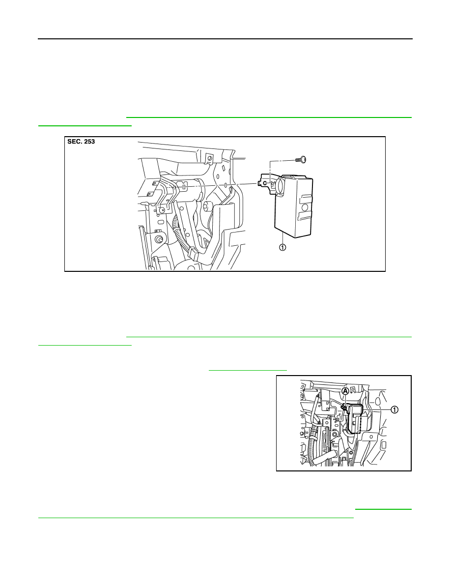
CAN GATEWAY
REMOVAL AND INSTALLATION
CAN GATEWAY
Exploded View
INFOID:0000000005241957
CAUTION:
Before replacing CAN gateway, perform “READ CONFIGURATION” to save or print current vehicle
specification. Refer to
LAN-98, "ADDITIONAL SERVICE WHEN REPLACING CONTROL UNIT (CAN
.
Removal and Installation
INFOID:0000000005241958
CAUTION:
Before replacing CAN gateway, perform “READ CONFIGURATION” to save or print current vehicle
specification. Refer to
LAN-98, "ADDITIONAL SERVICE WHEN REPLACING CONTROL UNIT (CAN
.
REMOVAL
1.
Remove instrument lower panel RH. Refer to
.
2.
Remove CAN gateway mounting screw (A).
3.
Remove CAN gateway (1) and disconnect the connector.
INSTALLATION
Install in the reverse order of removal.
CAUTION:
Be sure to perform “WRITE CONFIGURATION” when replacing CAN gateway. Refer to
TIONAL SERVICE WHEN REPLACING CONTROL UNIT (CAN GATEWAY) : Description"
1.
CAN gateway
JPMIA1063ZZ
JPMIA1064ZZ

LAN
MAIN LINE BETWEEN DLC AND M&A CIRCUIT
LAN-113
< DTC/CIRCUIT DIAGNOSIS >
[CAN SYSTEM (TYPE 1)]
C
D
E
F
G
H
I
J
K
L
B
A
O
P
N
DTC/CIRCUIT DIAGNOSIS
MAIN LINE BETWEEN DLC AND M&A CIRCUIT
Diagnosis Procedure
INFOID:0000000005576876
1.
CHECK HARNESS CONTINUITY (OPEN CIRCUIT)
1.
Turn the ignition switch OFF.
2.
Disconnect the battery cable from the negative terminal.
3.
Disconnect the following harness connectors.
-
ECM
-
Unified meter and A/C amp.
4.
Check the continuity between the data link connector and the unified meter and A/C amp. harness con-
nector.
Is the inspection result normal?
YES (Present error)>>Check CAN system type decision again.
YES (Past error)>>Error was detected in the main line between the data link connector and the unified meter
and A/C amp.
NO
>> Repair the main line between the data link connector and the unified meter and A/C amp.
Data link connector
Unified meter and A/C amp. harness connector
Continuity
Connector No.
Terminal No.
Connector No.
Terminal No.
M24
6
M67
56
Existed
14
72
Existed
Нет комментариевНе стесняйтесь поделиться с нами вашим ценным мнением.
Текст