Infiniti FX35, FX50 (S51). Manual — part 739
SNOW MODE SWITCH
EC-497
< DTC/CIRCUIT DIAGNOSIS >
[VQ35HR]
C
D
E
F
G
H
I
J
K
L
M
A
EC
N
P
O
Is the inspection result normal?
YES
>> GO TO 5.
NO
>> GO TO 4.
4.
DETECT MALFUNCTIONING PART
Check the following.
• Harness connectors E106, M6
• IPDM E/R harness connector E7
• 10 A fuse (No. 43)
• Harness for open or short between snow mode switch and fuse.
>> Repair open circuit, short to ground or short to power in harness or connectors.
5.
CHECK SNOW MODE SWITCH INPUT SIGNAL CIRCUIT FOR OPEN AND SHORT
1.
Turn ignition switch OFF.
2.
Disconnect “unified meter and A/C amp.” harness connector.
3.
Check the continuity between snow mode switch harness connector and “unified meter and A/C amp.”
harness connector.
4.
Also check harness for short to ground and short to power.
Is the inspection result normal?
YES
>> GO TO 8.
NO
>> Repair open circuit, short to ground or short to power in harness or connector.
6.
CHECK GROUND CONNECTION
1.
Turn ignition switch OFF.
2.
Check ground connection M95. Refer to Ground Inspection in
Is the inspection result normal?
YES
>> GO TO 7.
NO
>> Repair or replace ground connection.
7.
CHECK SNOW MODE INDICATOR LAMP GROUND CIRCUIT FOR OPEN AND SHORT
1.
Check the continuity between snow mode switch harness connector and ground.
2.
Also check harness for short to power.
Is the inspection result normal?
YES
>> GO TO 8.
NO
>> Repair open circuit or short to power in harness or connectors.
8.
CHECK SNOW MODE SWITCH
EC-498, "Component Inspection"
Is the inspection result normal?
YES
>> GO TO 9.
NO
>> Replace snow mode switch.
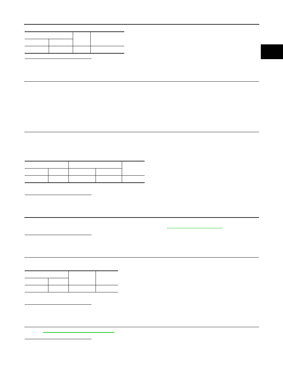
Snow mode switch
Ground
Voltage
Connector
Terminal
M176
1
Ground
Battery voltage
Snow mode switch
Unified meter and A/C amp.
Continuity
Connector
Terminal
Connector
Terminal
M176
4
M66
23
Existed
Snow mode switch
Ground
Continuity
Connector
Terminal
M176
2
Ground
Existed

EC-498
< DTC/CIRCUIT DIAGNOSIS >
[VQ35HR]
SNOW MODE SWITCH
9.
CHECK INTERMITTENT INCIDENT
GI-36, "Intermittent Incident"
>> INSPECTION END
Component Inspection
INFOID:0000000005237119
1.
CHECK SNOW MODE SWITCH
1.
Turn ignition switch OFF.
2.
Disconnect snow mode switch harness connector.
3.
Check the continuity between snow mode switch terminals under the following conditions.
Is the inspection result normal?
YES
>> INSPECTION END
NO
>> Replace snow mode switch.
Terminals
Condition
Continuity
1 and 4
Snow mode switch
ON
Existed
OFF
Not Existed
ECM
EC-499
< ECU DIAGNOSIS INFORMATION >
[VQ35HR]
C
D
E
F
G
H
I
J
K
L
M
A
EC
N
P
O
ECU DIAGNOSIS INFORMATION
ECM
Reference Value
INFOID:0000000005237120
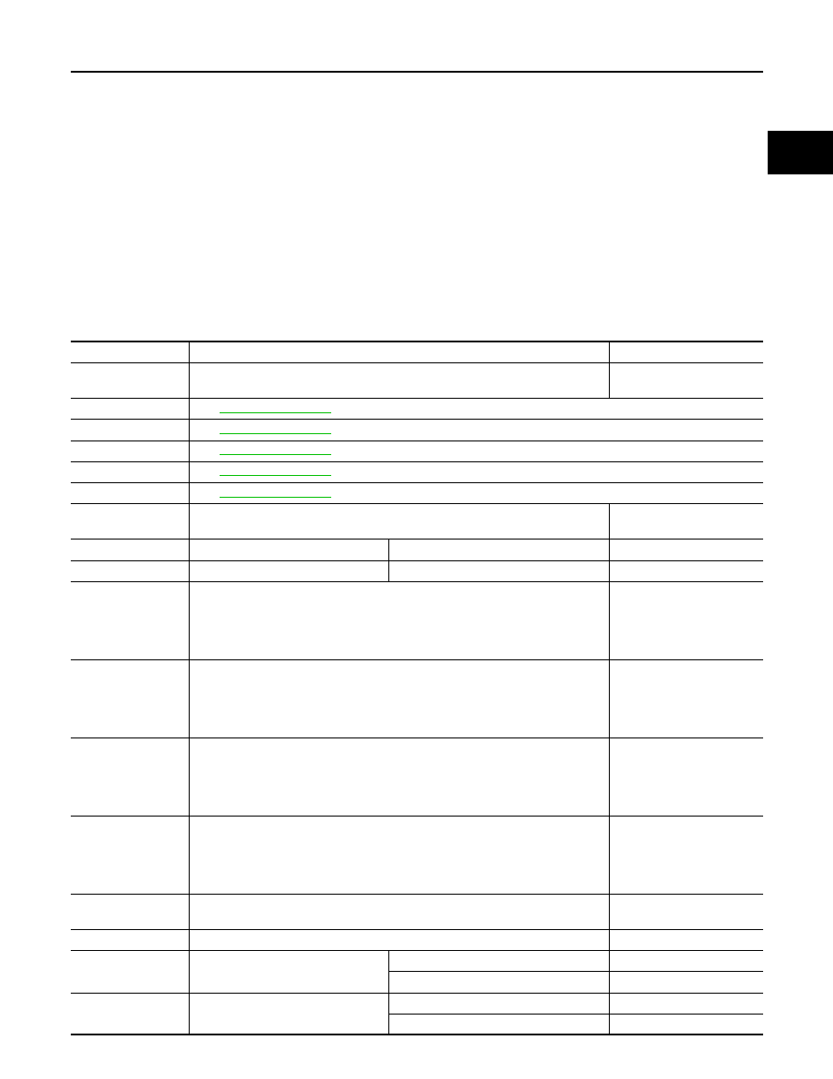
VALUES ON THE DIAGNOSIS TOOL
NOTE:
• Specification data are reference values.
• Specification data are output/input values which are detected or supplied by the ECM at the connector.
* Specification data may not be directly related to their components signals/values/operations.
i.e. Adjust ignition timing with a timing light before monitoring IGN TIMING, because the monitor may show
the specification data in spite of the ignition timing not being adjusted to the specification data. This IGN TIM-
ING monitors the data calculated by the ECM according to the signals input from the camshaft position sen-
sor and other ignition timing related sensors.
CONSULT-III MONITOR ITEM
Monitor Item
Condition
Values/Status
ENG SPEED
• Run engine and compare CONSULT-III value with the tachometer indication.
Almost the same speed as
the tachometer indication
MAS A/F SE-B1
.
MAS A/F SE-B2
.
B/FUEL SCHDL
.
A/F ALPHA-B1
.
A/F ALPHA-B2
.
COOLAN TEMP/S
• Ignition switch: ON
Indicates engine coolant
temperature
A/F SEN1 (B1)
• Engine: After warming up
Maintaining engine speed at 2,000 rpm
Fluctuates around 2.2 V
A/F SEN1 (B2)
• Engine: After warming up
Maintaining engine speed at 2,000 rpm
Fluctuates around 2.2 V
HO2S2 (B1)
• Revving engine from idle to 3,000 rpm quickly after the following conditions are
met.
- Engine: After warming up
- After keeping engine speed between 3,500 and 4,000 rpm for 1 minute and at
idle for 1 minute under no load
0 - 0.3 V
←→
Approx. 0.6 -
1.0 V
HO2S2 (B2)
• Revving engine from idle to 3,000 rpm quickly after the following conditions are
met.
- Engine: After warming up
- After keeping engine speed between 3,500 and 4,000 rpm for 1 minute and at
idle for 1 minute under no load
0 - 0.3 V
←→
Approx. 0.6 -
1.0 V
HO2S2 MNTR (B1)
• Revving engine from idle to 3,000 rpm quickly after the following conditions are
met.
- Engine: After warming up
- After keeping engine speed between 3,500 and 4,000 rpm for 1 minute and at
idle for 1 minute under no load
LEAN
←→
RICH
HO2S2 MNTR (B2)
• Revving engine from idle to 3,000 rpm quickly after the following conditions are
met.
- Engine: After warming up
- After keeping engine speed between 3,500 and 4,000 rpm for 1 minute and at
idle for 1 minute under no load
LEAN
←→
RICH
VHCL SPEED SE
• Turn drive wheels and compare CONSULT-III value with the speedometer indi-
cation.
Almost the same speed as
speedometer indication
BATTERY VOLT
• Ignition switch: ON (Engine stopped)
11 - 14 V
ACCEL SEN 1
• Ignition switch: ON
(Engine stopped)
Accelerator pedal: Fully released
0.45 - 1.0 V
Accelerator pedal: Fully depressed
4.4 - 4.8 V
ACCEL SEN 2*
1
• Ignition switch: ON
(Engine stopped)
Accelerator pedal: Fully released
0.45 - 1.0 V
Accelerator pedal: Fully depressed
4.4 - 4.8 V
EC-500
< ECU DIAGNOSIS INFORMATION >
[VQ35HR]
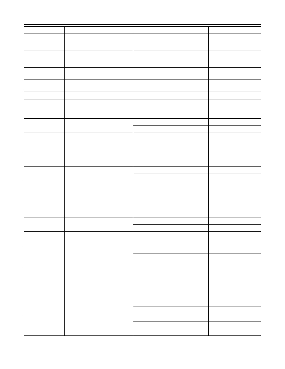
ECM
TP SEN 1-B1
• Ignition switch: ON
(Engine stopped)
• Selector lever: D
Accelerator pedal: Fully released
More than 0.36 V
Accelerator pedal: Fully depressed
Less than 4.75 V
TP SEN 2-B1*
1
• Ignition switch: ON
(Engine stopped)
• Selector lever: D
Accelerator pedal: Fully released
More than 0.36 V
Accelerator pedal: Fully depressed
Less than 4.75 V
FUEL T/TMP SE
• Ignition switch: ON
Indicates fuel tank tempera-
ture
INT/A TEMP SE
• Ignition switch: ON
Indicates intake air temper-
ature
EVAP SYS PRES
• Ignition switch: ON
Approx. 1.8 - 4.8 V
FUEL LEVEL SE
• Ignition switch: ON
Depending on fuel level of
fuel tank
START SIGNAL
• Ignition switch: ON
→
START
→
ON
OFF
→
ON
→
OFF
CLSD THL POS
• Ignition switch: ON
(Engine stopped)
Accelerator pedal: Fully released
ON
Accelerator pedal: Slightly depressed
OFF
AIR COND SIG
• Engine: After warming up, idle the
engine
Air conditioner switch: OFF
OFF
Air conditioner switch: ON
(Compressor operates.)
ON
P/N POSI SW
• Ignition switch: ON
Selector lever: P or N
ON
Selector lever: Except above
OFF
PW/ST SIGNAL
• Engine: After warming up, idle the
engine
Steering wheel: Not being turned
OFF
Steering wheel: Being turned
ON
LOAD SIGNAL
• Ignition switch: ON
Rear window defogger switch: ON
and/or
Lighting switch: 2nd position
ON
Rear window defogger switch and lighting
switch: OFF
OFF
IGNITION SW
• Ignition switch: ON
→
OFF
→
ON
ON
→
OFF
→
ON
HEATER FAN SW
• Engine: After warming up, idle the
engine
Heater fan switch: ON
ON
Heater fan switch: OFF
OFF
BRAKE SW
• Ignition switch: ON
Brake pedal: Fully released
OFF
Brake pedal: Slightly depressed
ON
INJ PULSE-B1
• Engine: After warming up
• Selector lever: P or N
• Air conditioner switch: OFF
• No load
Idle
2.0 - 3.0 msec
2,000 rpm
1.9 - 2.9 msec
INJ PULSE-B2
• Engine: After warming up
• Selector lever: P or N
• Air conditioner switch: OFF
• No load
Idle
2.0 - 3.0 msec
2,000 rpm
1.9 - 2.9 msec
IGN TIMING
• Engine: After warming up
• Selector lever: P or N
• Air conditioner switch: OFF
• No load
Idle
6
°
- 16
°
BTDC (With 4WAS)
10
°
- 20
°
BTDC (Without
4WAS)
2,000 rpm
25
°
- 45
°
BTDC
CAL/LD VALUE
• Engine: After warming up
• Selector lever: P or N
• Air conditioner switch: OFF
• No load
Idle
5% - 35%
2,500 rpm
5% - 35%
Monitor Item
Condition
Values/Status
Нет комментариевНе стесняйтесь поделиться с нами вашим ценным мнением.
Текст