Infiniti FX35, FX50 (S51). Manual — part 924
EVAP LEAK CHECK
EC-1237
< PERIODIC MAINTENANCE >
[VK50VE]
C
D
E
F
G
H
I
J
K
L
M
A
EC
N
P
O
EVAP LEAK CHECK
Inspection
INFOID:0000000005237667
CAUTION:
• Do not use compressed air or a high pressure pump.
• Do not exceed 4.12 kPa (0.042 kg/cm
2
, 0.6 psi) of pressure in EVAP system.
NOTE:
• Do not start engine.
• Improper installation of EVAP service port adapter (commercial service tool) to the EVAP service port may
cause a leak.
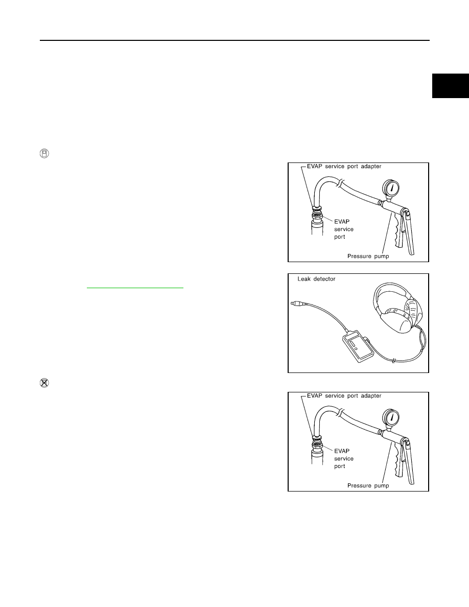
WITH CONSULT-III
1.
To locate the EVAP leak, install EVAP service port adapter (com-
mercial service tool) and pressure pump to EVAP service port.
2.
Turn ignition switch ON.
3.
Select the “EVAP SYSTEM CLOSE” of “WORK SUPPORT”
mode with CONSULT-III.
4.
Touch “START”. A bar graph (Pressure indicating display) will
appear on the screen.
5.
Apply positive pressure to the EVAP system until the pressure
indicator reaches the middle of the bar graph.
6.
Remove EVAP service port adapter (commercial service tool)
and hose with pressure pump.
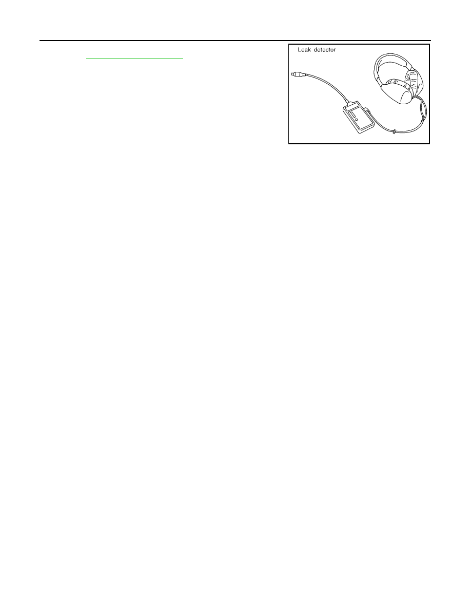
7.
Locate the leak using a leak detector (commercial service tool).
Refer to
.
WITHOUT CONSULT-III
1.
To locate the EVAP leak, install EVAP service port adapter (com-
mercial service tool) and pressure pump to EVAP service port.
2.
Apply battery voltage between the terminals of EVAP canister
vent control valve to make a closed EVAP system.
3.
To locate the leak, deliver positive pressure to the EVAP system
until pressure gauge points reach 1.38 to 2.76 kPa (0.014 to
0.028 kg/cm
2
, 0.2 to 0.4 psi).
4.
Remove EVAP service port adapter (commercial service tool)
and hose with pressure pump.
SEF462UA
SEF200U
SEF462UA
EC-1238
< PERIODIC MAINTENANCE >
[VK50VE]
EVAP LEAK CHECK
5.
Locate the leak using a leak detector (commercial service tool).
Refer to
.
SEF200U
EVAP CANISTER
EC-1239
< REMOVAL AND INSTALLATION >
[VK50VE]
C
D
E
F
G
H
I
J
K
L
M
A
EC
N
P
O
REMOVAL AND INSTALLATION
EVAP CANISTER
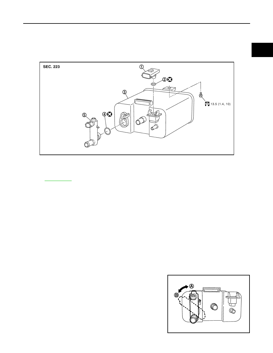
Exploded View
INFOID:0000000005237668
Removal and Installation
INFOID:0000000005237669
REMOVAL
1.
Lift up the vehicle.
2.
Remove EVAP canister fixing bolt.
3.
Remove EVAP canister.
NOTE:
The EVAP canister vent control valve and EVAP control system pressure sensor can be removed without
removing the EVAP canister.
INSTALLATION
Install in the reverse order of removal.
NOTE:
Tighten EVAP canister fixing bolt to the specified torque.
DISASSEMBLY
1.
Turn EVAP canister vent control valve counterclockwise.
• Lock (A)
• Unlock (B)
2.
Remove the EVAP canister vent control valve.
1.
EVAP control system pressure sen-
sor
2.
O-ring
3.
EVAP canister
4.
O-ring
5.
EVAP canister vent control valve
Refer to
for symbols not described on the above.
JMBIA0049GB
PBIB2730E
EC-1240
< REMOVAL AND INSTALLATION >
[VK50VE]
EVAP CANISTER
ASSEMBLY
Assemble in the reverse order of disassembly.
CAUTION:
Always replace O-ring with a new one.
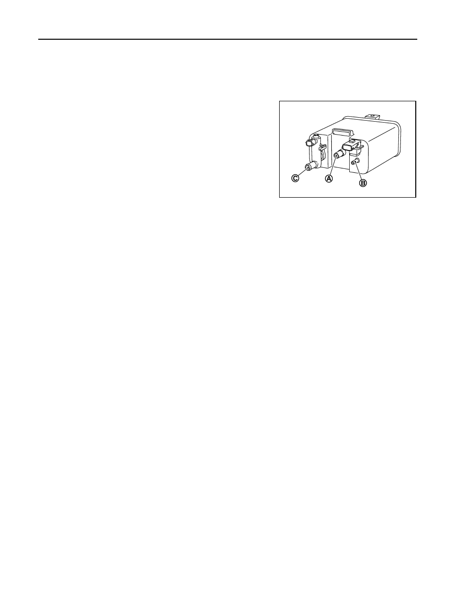
Inspection
INFOID:0000000005237670
Check EVAP canister as per the following:
1.
Block port (B).
2.
Blow air into port (A) and check that it flows freely out of port (C).
3.
Release blocked port (B).
4.
Apply vacuum pressure to port (B) and check that vacuum pres-
sure exists at the ports (A) and (C).
5.
Block port (A) and (B).
6.
Apply pressure to port (C) and check that there is no leakage.
PBIB2728E
Нет комментариевНе стесняйтесь поделиться с нами вашим ценным мнением.
Текст