Infiniti FX35, FX50 (S51). Manual — part 897
SNOW MODE SWITCH
EC-1129
< DTC/CIRCUIT DIAGNOSIS >
[VK50VE]
C
D
E
F
G
H
I
J
K
L
M
A
EC
N
P
O
SNOW MODE SWITCH
Description
INFOID:0000000005237644
The snow mode switch signal is sent to the “unified meter and A/C amp.” from the snow mode switch. The
“unified meter and A/C amp.” then sends the signal to the ECM via the CAN communication line.
The snow mode is used for driving or starting the vehicle on snowy roads or slippery areas. If the snow mode
is activated, the vehicle speed will not accelerate as quickly as normal to avoid vehicle slip. In other words,
ECM controls rapid engine torque change by controlling the electric throttle control actuator operating speed.
Component Function Check
INFOID:0000000005237645
1.
CHECK SNOW MODE SWITCH FUNCTION
NOTE:
If DTC UXXXX are displayed, first perform the trouble diagnosis for DTC UXXXX.
1.
Turn ignition switch ON.
2.
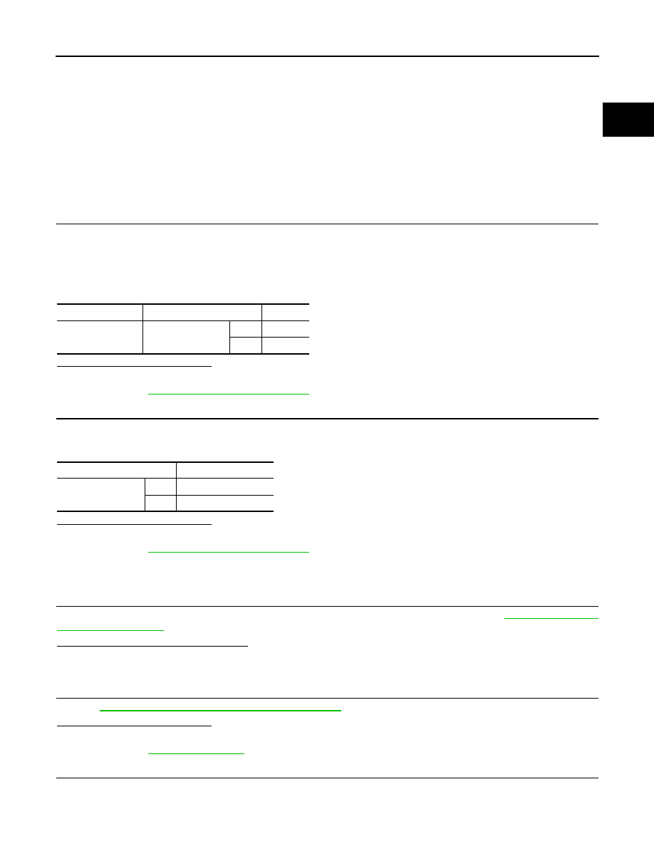
Select “SNOW MODE SW” in “DATA MONITOR” mode with CONSULT-III.
3.
Check “SNOW MODE SW” indication under the following conditions.
Is the inspection result normal?
YES
>> GO TO 2.
NO
>> Go to
EC-1129, "Diagnosis Procedure"
.
2.
CHECK SNOW MODE INDICATOR FUNCTION
1.
Turn ignition switch ON.
2.
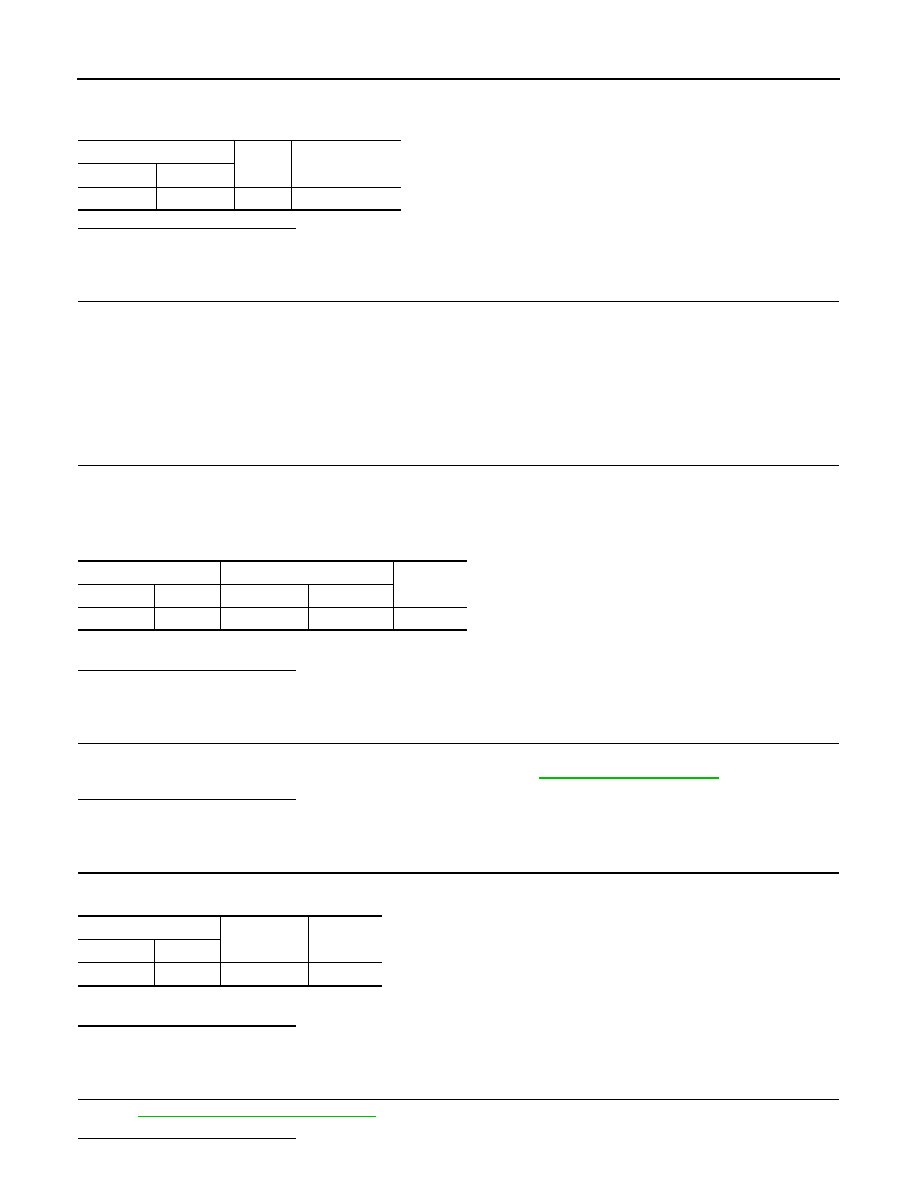
Check the snow mode indicator in the snow mode switch under the following condition.
Is the inspection result normal?
YES
>> INSPECTION END
NO
>> Go to
EC-1129, "Diagnosis Procedure"
.
Diagnosis Procedure
INFOID:0000000005237646
1.
CHECK SNOW MODE SWITCH OVERALL FUNCTION-I
Confirm the malfunctioning circuit (snow mode switch or snow mode indicator). Refer to
Which circuit is related to the incident?
Snow mode switch>>GO TO 2.
Snow mode indicator>>GO TO 6.
2.
CHECK DTC WITH “UNIFIED METER AND A/C AMP.”
MWI-45, "CONSULT-III Function (METER/M&A)"
.
Is the inspection result normal?
YES
>> GO TO 3.
NO
>> Go to
3.
CHECK SNOW MODE SWITCH POWER SUPPLY CIRCUIT
1.
Turn ignition switch OFF.
2.
Disconnect snow mode switch harness connector.
Monitor item
Condition
Indication
SNOW MODE SW
Snow mode switch
ON
ON
OFF
OFF
Condition
Snow mode indicator
Snow mode switch
ON
ON
OFF
OFF
EC-1130
< DTC/CIRCUIT DIAGNOSIS >
[VK50VE]
SNOW MODE SWITCH
3.
Turn ignition switch ON.
4.
Check the voltage between snow mode switch harness connector and ground.
Is the inspection result normal?
YES
>> GO TO 5.
NO
>> GO TO 4.
4.
DETECT MALFUNCTIONING PART
Check the following.
• Harness connectors E106, M6
• IPDM E/R harness connector E7
• 10 A fuse (No. 43)
• Harness for open or short between snow mode switch and fuse.
>> Repair open circuit, short to ground or short to power in harness or connectors.
5.
CHECK SNOW MODE SWITCH INPUT SIGNAL CIRCUIT FOR OPEN AND SHORT
1.
Turn ignition switch OFF.
2.
Disconnect “unified meter and A/C amp.” harness connector.
3.
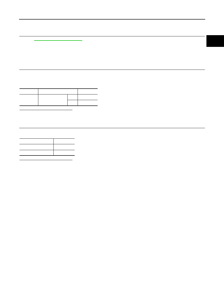
Check the continuity between snow mode switch harness connector and “unified meter and A/C amp.”
harness connector.
4.
Also check harness for short to ground and short to power.
Is the inspection result normal?
YES
>> GO TO 8.
NO
>> Repair open circuit, short to ground or short to power in harness or connectors.
6.
CHECK GROUND CONNECTION
1.
Turn ignition switch OFF.
2.
Check ground connection M95. Refer to Ground Inspection in
Is the inspection result normal?
YES
>> GO TO 7.
NO
>> Repair or replace ground connection.
7.
CHECK SNOW MODE INDICATOR LAMP GROUND CIRCUIT FOR OPEN AND SHORT
1.
Check the continuity between snow mode switch harness connector and ground.
2.
Also check harness for short to power.
Is the inspection result normal?
YES
>> GO TO 8.
NO
>> Repair open circuit or short to power in harness or connectors.
8.
CHECK SNOW MODE SWITCH
EC-1131, "Component Inspection"
.
Is the inspection result normal?
Snow mode switch
Ground
Voltage
Connector
Terminal
M176
1
Ground
Battery voltage
Snow mode switch
Unified meter and A/C amp.
Continuity
Connector
Terminal
Connector
Terminal
M176
4
M66
23
Existed
Snow mode switch
Ground
Continuity
Connector
Terminal
M176
2
Ground
Existed
SNOW MODE SWITCH
EC-1131
< DTC/CIRCUIT DIAGNOSIS >
[VK50VE]
C
D
E
F
G
H
I
J
K
L
M
A
EC
N
P
O
YES
>> GO TO 9.
NO
>> Replace snow mode switch.
9.
CHECK INTERMITTENT INCIDENT
GI-36, "Intermittent Incident"
.
>> INSPECTION END
Component Inspection
INFOID:0000000005237647
1.
CHECK SNOW MODE SWITCH-I
1.
Turn ignition switch OFF.
2.
Disconnect snow mode switch harness connector.
3.
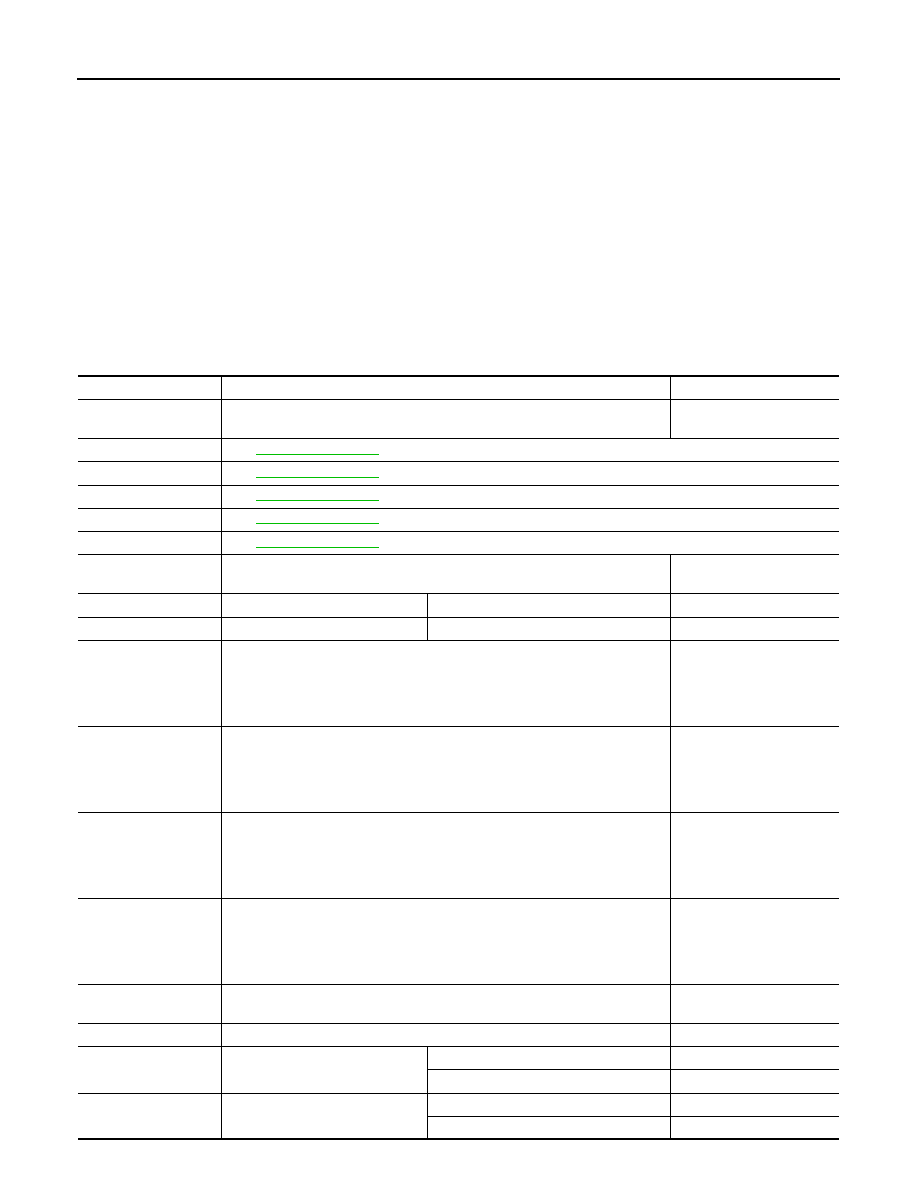
Check the continuity between snow mode switch terminals under the following conditions.
Is the inspection result normal?
YES
>> GO TO 2.
NO
>> Replace snow mode switch.
2.
CHECK SNOW MODE SWITCH-II
Check the continuity between snow mode switch terminals under the following conditions.
Is the inspection result normal?
YES
>> INSPECTION END
NO
>> Replace snow mode switch.
Terminals
Condition
Continuity
1 and 4
Snow mode switch
ON
Existed
OFF
Not Existed
Terminals (Polarity)
Continuity
2 (+) - 4 (–)
Existed
4 (+) - 2 (–)
Not Existed
EC-1132
< ECU DIAGNOSIS INFORMATION >
[VK50VE]
ECM
ECU DIAGNOSIS INFORMATION
ECM
Reference Value
INFOID:0000000005237648
VALUES ON THE DIAGNOSIS TOOL
NOTE:
• Specification data are reference values.
• Specification data are output/input values which are detected or supplied by the ECM at the connector.
* Specification data may not be directly related to their components signals/values/operations.
i.e. Adjust ignition timing with a timing light before monitoring IGN TIMING, because the monitor may show
the specification data in spite of the ignition timing not being adjusted to the specification data. This IGN TIM-
ING monitors the data calculated by the ECM according to the signals input from the camshaft position sen-
sor and other ignition timing related sensors.
CONSULT-III MONITOR ITEM
Monitor Item
Condition
Values/Status
ENG SPEED
• Run engine and compare CONSULT-III value with the tachometer indication.
Almost the same speed as
the tachometer indication
MAS A/F SE-B1
MAS A/F SE-B2
B/FUEL SCHDL
A/F ALPHA-B1
A/F ALPHA-B2
COOLAN TEMP/S
• Ignition switch: ON
Indicates engine coolant
temperature
A/F SEN1 (B1)
• Engine: After warming up
Maintaining engine speed at 2,000 rpm
Fluctuates around 2.2 V
A/F SEN1 (B2)
• Engine: After warming up
Maintaining engine speed at 2,000 rpm
Fluctuates around 2.2 V
HO2S2 (B1)
• Revving engine from idle up to 3,000 rpm quickly after the following condi-
tions are met.
- Engine: After warming up
- After keeping engine speed between 3,500 and 4,000 rpm for 1 minute and
at idle for 1 minute under no load
0 - 0.3 V
←→
Approx. 0.6 -
1.0 V
HO2S2 (B2)
• Revving engine from idle up to 3,000 rpm quickly after the following condi-
tions are met.
- Engine: After warming up
- After keeping engine speed between 3,500 and 4,000 rpm for 1 minute and
at idle for 1 minute under no load
0 - 0.3 V
←→
Approx. 0.6 -
1.0 V
HO2S2 MNTR (B1)
• Revving engine from idle up to 3,000 rpm quickly after the following condi-
tions are met.
- Engine: After warming up
- After keeping engine speed between 3,500 and 4,000 rpm for 1 minute and
at idle for 1 minute under no load
LEAN
←→
RICH
HO2S2 MNTR (B2)
• Revving engine from idle up to 3,000 rpm quickly after the following condi-
tions are met.
- Engine: After warming up
- After keeping engine speed between 3,500 and 4,000 rpm for 1 minute and
at idle for 1 minute under no load
LEAN
←→
RICH
VHCL SPEED SE
• Turn drive wheels and compare CONSULT-III value with the speedometer in-
dication.
Almost the same speed as
speedometer indication
BATTERY VOLT
• Ignition switch: ON (Engine stopped)
11 - 14 V
ACCEL SEN 1
• Ignition switch: ON
(Engine stopped)
Accelerator pedal: Fully released
0.45 - 1.0 V
Accelerator pedal: Fully depressed
4.4 - 4.8 V
ACCEL SEN 2*
1
• Ignition switch: ON
(Engine stopped)
Accelerator pedal: Fully released
0.45 - 1.0 V
Accelerator pedal: Fully depressed
4.3 - 4.8 V
Нет комментариевНе стесняйтесь поделиться с нами вашим ценным мнением.
Текст