Infiniti FX35, FX50 (S51). Manual — part 66

AV
AV CONTROL UNIT
AV-37
< ECU DIAGNOSIS INFORMATION >
[WITHOUT NAVIGATION]
C
D
E
F
G
H
I
J
K
L
M
B
A
O
P
7
(V)
Ground
ACC power supply
Input
Ignition
switch
ACC
—
Battery voltage
9
(R)
Ground
Illumination signal
Input
Ignition
switch
OFF
Lighting switch is OFF.
0 V
Lighting switch is ON.
12.0 V
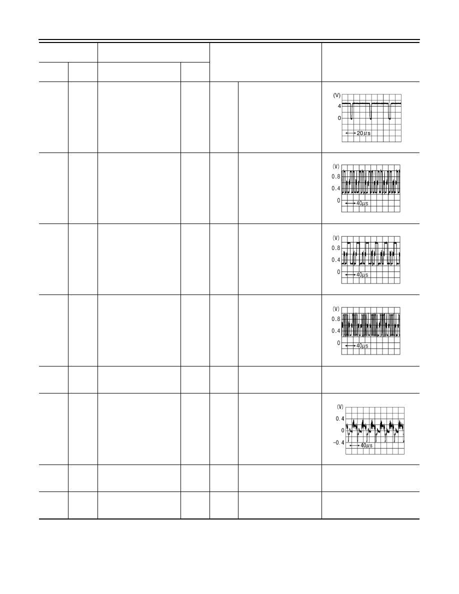
16
(L)
15
(B)
Steering switch signal B
Input
Ignition
switch
ON
Keep pressing VOL DOWN
switch.
0 V
Keep pressing VOL UP
switch.
0.7 V
Keep pressing
switch.
1.3 V
Except for above.
3.3 V
19
(Y)
Ground
Battery power supply
Input
Ignition
switch
OFF
—
Battery voltage
20
(B)
Ground
Ground
—
Ignition
switch
ON
—
0 V
36
(O)
Ground
Signal VCC
Output
Ignition
switch
ACC
—
8.8 V
37
(LG)
Ground
Signal ground
—
Ignition
switch
OFF
—
0 V
38
(R)
Ground
Horizontal synchronizing
(HP) signal
Input
Ignition
switch
ON
—
39
(BR)
Ground
Communication signal
(DISP
→
CONT)
Input
Ignition
switch
ON
When adjusting display
brightness.
40
(B)
Ground
RGB area (YS) signal
Output
Ignition
switch
ON
At RGB image is displayed.
5.0 V
At AUX image is displayed.
41
—
Shield
—
—
—
—
Terminal
(Wire color)
Description
Condition
Reference value
(Approx.)
+
–
Signal name
Input/
Output
SKIB3601E
PKIB5039J
PKIB4948J
AV-38
< ECU DIAGNOSIS INFORMATION >
[WITHOUT NAVIGATION]
AV CONTROL UNIT
42
(G)
Ground
RGB synchronizing signal
Output
Ignition
switch
ON
—
43
(B)
Ground
RGB signal (R: red)
Output
Ignition
switch
ON
Start Confirmation/Adjust-
ment mode, and then dis-
play color bar by selecting
“Color Spectrum Bar” on
Display Diagnosis screen.
44
(W)
Ground
RGB signal (G: green)
Output
Ignition
switch
ON
Start Confirmation/Adjust-
ment mode, and then dis-
play color bar by selecting
“Color Spectrum Bar” on
Display Diagnosis screen.
45
(R)
Ground
RGB signal (B: blue)
Output
Ignition
switch
ON
Start Confirmation/Adjust-
ment mode, and then dis-
play color bar by selecting
“Color Spectrum Bar” on
Display Diagnosis screen.
46
(V)
Ground
Composite image signal
ground
—
Ignition
switch
ON
—
0 V
47
(SB)
Ground
Composite image signal
Output
Ignition
switch
ON
At camera image is dis-
played.
48
(Y)
Ground
Inverter VCC
Output
Ignition
switch
ACC
—
8.8 V
49
(BR)
Ground
Inverter ground
—
Ignition
switch
OFF
—
0 V
Terminal
(Wire color)
Description
Condition
Reference value
(Approx.)
+
–
Signal name
Input/
Output
SKIB3603E
JSNIA1029ZZ
JSNIA1030ZZ
JSNIA1031ZZ
SKIB2251J
AV
AV CONTROL UNIT
AV-39
< ECU DIAGNOSIS INFORMATION >
[WITHOUT NAVIGATION]
C
D
E
F
G
H
I
J
K
L
M
B
A
O
P
50
(W)
Ground
Vertical synchronizing (VP)
signal
Input
Ignition
switch
ON
—
51
(Y)
Ground
Communication signal
(CONT
→
DISP)
Output
Ignition
switch
ON
When adjusting display
brightness.
52
—
Shield
—
—
—
—
57
—
Shield
—
—
—
—
58
—
Shield
—
—
—
—
61
(Y)
Ground
AUX image signal
Input
Ignition
switch
ON
At AUX image is displayed.
62
(W)
Ground
Camera image signal
Input
Ignition
switch
ON
At camera image is dis-
played.
63
—
Shield
—
—
—
—
69
(BR)
Ground
AUX image signal ground
—
Ignition
switch
ON
—
0 V
70
—
Shield
—
—
—
—
72
(B)
—
Camera ground
—
Ignition
switch
ON
—
0 V
73
(R)
Ground
Camera power supply
Output
Ignition
switch
ON
At camera image is dis-
played.
76
(LG)
—
AV communication signal
(L)
Input/
Output
—
—
—
Terminal
(Wire color)
Description
Condition
Reference value
(Approx.)
+
–
Signal name
Input/
Output
SKIB3598E
PKIB5039J
SKIB2251J
SKIB2251J
SKIB2251J

AV-40
< ECU DIAGNOSIS INFORMATION >
[WITHOUT NAVIGATION]
AV CONTROL UNIT
77
(SB)
—
AV communication signal
(H)
Input/
Output
—
—
—
78
(LG)
—
AV communication signal
(L)
Input/
Output
—
—
—
79
(SB)
—
AV communication signal
(H)
Input/
Output
—
—
—
80
(P)
—
CAN–L
Input/
Output
—
—
—
81
(L)
—
CAN–H
Input/
Output
—
—
—
82
(BR)
Ground
Switch ground
—
Ignition
switch
ON
—
0 V
86
—
Shield
—
—
—
—
87
(L)
88
(P)
TEL voice signal
Input
Ignition
switch
ON
During voice guide output
with the
switch
pressed.
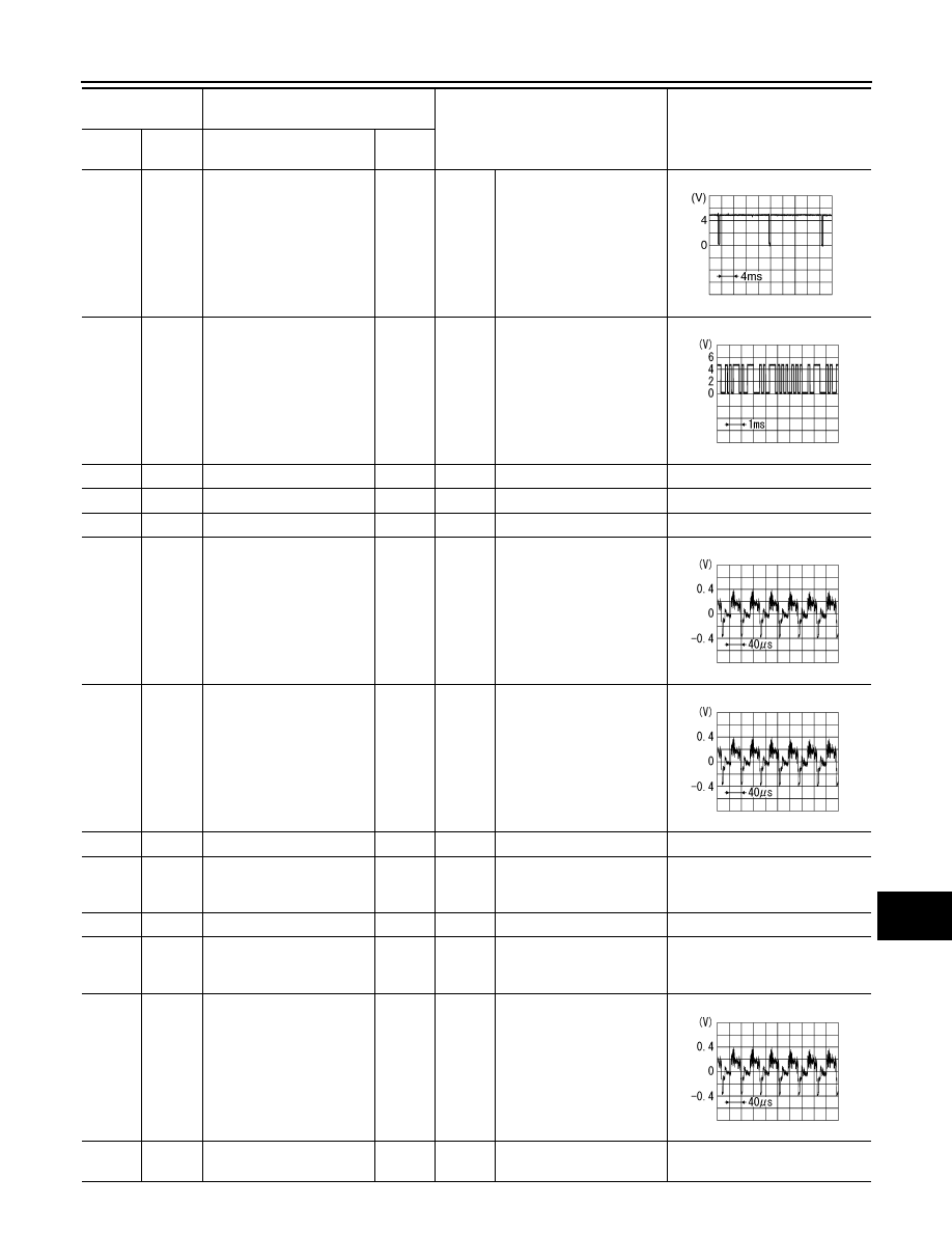
92
(R)
Ground
Vehicle speed signal (8-
pulse)
Input
Ignition
switch
ON
When vehicle speed is ap-
prox. 40 km/h (25 MPH)
NOTE:
Maximum voltage may be 12.0 V
due to specifications (connected
units).
93
(V)
Ground
Parking brake signal
Input
Ignition
switch
ON
Parking brake is ON.
4.5 V
Parking brake is OFF.
0 V
94
(O)
Ground
Reverse signal
Input
Ignition
switch
ON
Shift the selector lever to R
position.
12.0 V
Shift the selector lever oth-
er than R position.
0 V
95
(G)
Ground
Ignition signal
Input
Ignition
switch
ON
—
Battery voltage
96
(SB)
Ground
Disk eject signal
Input
Ignition
switch
ON
Pressing the eject switch.
0 V
Except for above.
5.0 V
Terminal
(Wire color)
Description
Condition
Reference value
(Approx.)
+
–
Signal name
Input/
Output
SKIB3609E
SKIA6649J
Нет комментариевНе стесняйтесь поделиться с нами вашим ценным мнением.
Текст