Infiniti FX35, FX50 (S51). Manual — part 1522
POWER SUPPLY AND GROUND CIRCUIT
PWC-149
< DTC/CIRCUIT DIAGNOSIS >
[FRONT WINDOW ANTI-PINCH]
C
D
E
F
G
H
I
J
L
M
A
B
PWC
N
O
P
3.
Turn ignition switch ON.
4.
Check voltage between power window main switch harness connector and ground.
Is the inspection result normal?
YES
>> GO TO 2.
NO
>> GO TO 3.
2.
CHECK GROUND CIRCUIT
1.
Turn ignition switch OFF.
2.
Check continuity between power window main switch harness connector and ground.
Is the inspection result normal?
YES
>> GO TO 4.
NO
>> Repair or replace harness.
3.
CHECK POWER SUPPLY CIRCUIT 2
1.
Turn ignition switch OFF.
2.
Disconnect BCM connector.
3.
Check continuity between BCM harness connector and power window main switch harness connector.
4.
Check continuity between BCM harness connector and ground.
Is the inspection result normal?
YES
>> Replace BCM. Refer to
.
NO
>> Repair or replace harness.
4.
CHECK INTERMITTENT INCIDENT
GI-36, "Intermittent Incident"
>> INSPECTION END
FRONT POWER WINDOW SWITCH (PASSENGER SIDE)
FRONT POWER WINDOW SWITCH (PASSENGER SIDE) : Diagnosis Procedure
INFOID:0000000005248265
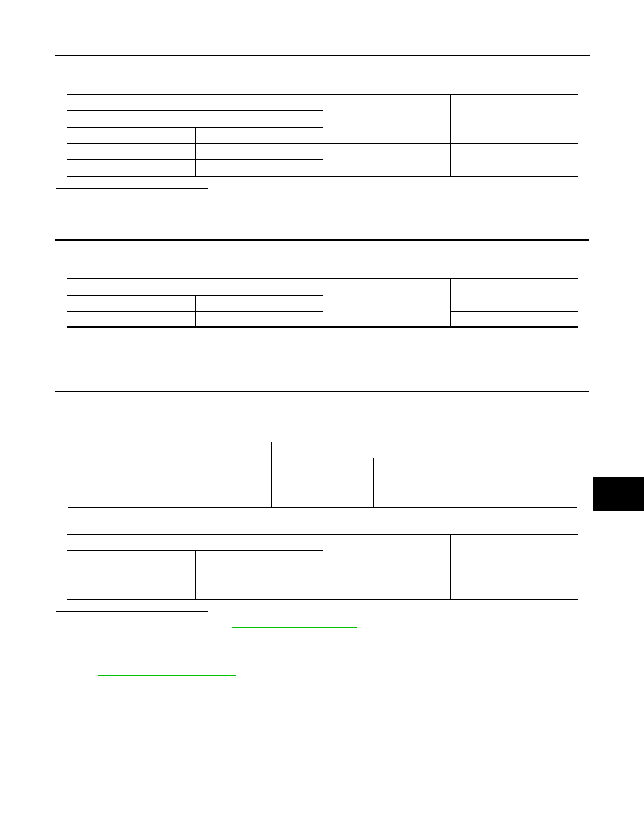
1.
CHECK POWER SUPPLY CIRCUIT 1
1.
Turn ignition switch OFF.
(+)
(–)
Voltage (V)
(Approx.)
Power window main switch
Connector
Terminal
D8
10
Ground
Battery voltage
D9
19
Power window main switch
Ground
Continuity
Connector
Terminal
D9
17
Existed
BCM
Power window main switch
Continuity
Connector
Terminal
Connector
Terminal
M118
2
D9
19
Existed
3
D8
10
BCM
Ground
Continuity
Connector
Terminal
M118
2
Not existed
3

PWC-150
< DTC/CIRCUIT DIAGNOSIS >
[FRONT WINDOW ANTI-PINCH]
POWER SUPPLY AND GROUND CIRCUIT
2.
Disconnect front power window switch (passenger side) connector.
3.
Check voltage between front power window switch (passenger side) harness connector and ground.
Is the inspection result normal?
YES
>> GO TO 2.
NO
>> GO TO 3.
2.
CHECK GROUND CIRCUIT
Check continuity between front power window switch (passenger side) harness connector and ground.
Is the inspection result normal?
YES
>> GO TO 4.
NO
>> Repair or replace harness.
3.
CHECK POWER SUPPLY CIRCUIT 2
1.
Disconnect BCM connector.
2.
Check continuity between BCM harness connector and front power window switch (passenger side) har-
ness connector.
3.
Check continuity between BCM harness connector and ground.
Is the inspection result normal?
YES
>> Replace BCM. Refer to
NO
>> Repair or replace harness.
4.
CHECK INTERMITTENT INCIDENT
GI-36, "Intermittent Incident"
>> INSPECTION END
REAR POWER WINDOW SWITCH
REAR POWER WINDOW SWITCH : Diagnosis Procedure
INFOID:0000000005248266
1.
CHECK POWER SUPPLY CIRCUIT 1
1.
Turn ignition switch OFF.
2.
Disconnect rear power window switch connectors.
3.
Turn ignition switch ON.
4.
Check voltage between rear power window switch harness connector and ground.
(+)
(–)
Voltage (V)
(Approx.)
Front power window switch
(passenger side)
Connector
Terminal
D38
10
Ground
Battery voltage
Front power window switch
(passenger side)
Ground
Continuity
Connector
Terminal
D38
11
Existed
BCM
Front power window switch
(passenger side)
Continuity
Connector
Terminal
Connector
Terminal
M118
2
D38
10
Existed
BCM
Ground
Continuity
Connector
Terminal
M118
2
Not existed

POWER SUPPLY AND GROUND CIRCUIT
PWC-151
< DTC/CIRCUIT DIAGNOSIS >
[FRONT WINDOW ANTI-PINCH]
C
D
E
F
G
H
I
J
L
M
A
B
PWC
N
O
P
Is the inspection result normal?
YES
>> GO TO 2.
NO
>> GO TO 3.
2.
CHECK GROUND CIRCUIT
Check continuity between rear power window switch harness connector and ground.
Is the inspection result normal?
YES
>> GO TO 4.
NO
>> Repair or replace harness.
3.
CHECK POWER SUPPLY CIRCUIT 2
1.
Turn ignition switch OFF.
2.
Disconnect BCM connector.
3.
Check continuity between BCM harness connector and rear power window switch harness connector.
4.
Check continuity between BCM harness connector and ground.
Is the inspection result normal?
YES
>> Replace BCM. Refer to
.
NO
>> Repair or replace harness.
4.
CHECK INTERMITTENT INCIDENT
GI-36, "Intermittent Incident"
>> INSPECTION END
(+)
(–)
Voltage (V)
(Approx.)
Rear power window switch
Connector
Terminal
LH
D54
1
Ground
Battery voltage
RH
D74
Rear power window switch
Ground
Continuity
Connector
Terminal
LH
D54
7
Existed
RH
D74
BCM
Rear power window switch
Continuity
Connector
Terminal
Connector
Terminal
M118
3
LH
D54
1
Existed
RH
D74
BCM
Ground
Continuity
Connector
Terminal
M118
3
Not existed
PWC-152
< DTC/CIRCUIT DIAGNOSIS >
[FRONT WINDOW ANTI-PINCH]
REAR POWER WINDOW SWITCH
REAR POWER WINDOW SWITCH
Description
INFOID:0000000005248267
• BCM supplies power.
• When power window switch is operated, corresponding power window motor is activated and rear door
glass moves UP/DOWN.
Component Function Check
INFOID:0000000005248268
1.
CHECK REAR POWER WINDOW FUNCTION
Check rear power window motor operation with rear power window switch.
Is the inspection result normal?
YES
>> Rear power window switch is OK.
NO
>> Refer to
PWC-152, "Diagnosis Procedure"
.
Diagnosis Procedure
INFOID:0000000005248269
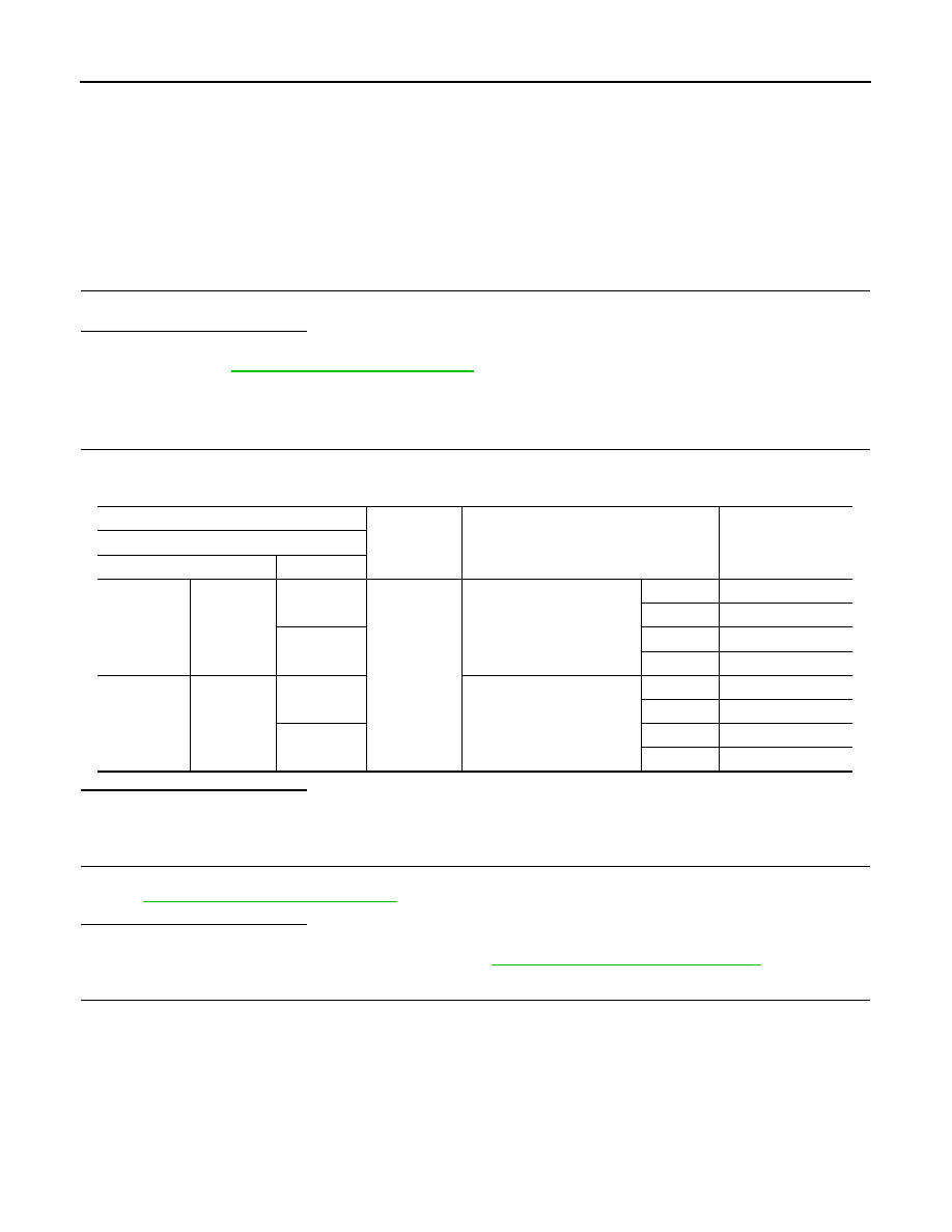
1.
CHECK REAR POWER WINDOW MOTOR INPUT SIGNAL
1.
Turn ignition switch ON.
2.
Check voltage between rear power window switch harness connector and ground.
Is the inspection result normal?
YES
>> GO TO 2.
NO
>> GO TO 3.
2.
CHECK REAR POWER WINDOW SWITCH
Check rear power window switch.
Refer to
PWC-153, "Component Inspection"
.
Is the inspection result normal?
YES
>> GO TO 4.
NO
>> Replace rear power window switch. Refer to
PWC-251, "Removal and Installation"
3.
CHECK HARNESS CONTINUITY
1.
Turn ignition switch OFF.
2.
Disconnect power window main switch connector and rear power window switch connector.
3.
Check continuity between power window main switch harness connector and rear power window switch
harness connector.
(+)
(–)
Condition
Voltage (V)
(Approx.)
Rear power window switch
Connector
Terminal
LH
D54
2
Ground
Power window main switch
(rear LH)
UP
Battery voltage
DOWN
0
3
UP
0
DOWN
Battery voltage
RH
D74
2
Power window main switch
(rear RH)
UP
Battery voltage
DOWN
0
3
UP
0
DOWN
Battery voltage
Нет комментариевНе стесняйтесь поделиться с нами вашим ценным мнением.
Текст