Infiniti FX35, FX50 (S51). Manual — part 1950

DIAGNOSIS SYSTEM (IPDM E/R)
WW-23
< SYSTEM DESCRIPTION >
C
D
E
F
G
H
I
J
K
M
A
B
WW
N
O
P
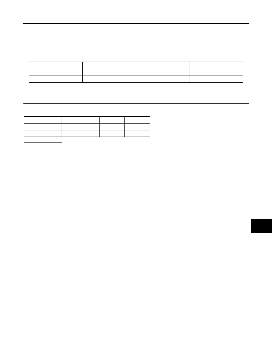
ACTIVE TEST
Test item
IGN RLY1 -REQ
[Off/On]
Displays the status of the ignition switch ON signal received from BCM via CAN
communication.
IGN RLY
[Off/On]
×
Displays the status of the ignition relay judged by IPDM E/R.
PUSH SW
[Off/On]
Displays the status of the push-button ignition switch judged by IPDM E/R.
INTER/NP SW
[Off/On]
Displays the status of the shift position judged by IPDM E/R.
ST RLY CONT
[Off/On]
Displays the status of the starter relay status signal received from BCM via CAN
communication.
IHBT RLY -REQ
[Off/On]
Displays the status of the starter control relay signal received from BCM via CAN
communication.
ST/INHI RLY
[Off/ ST /INHI/UNKWN]
Displays the status of the starter relay and starter control relay judged by IPDM
E/R.
DETENT SW
[Off/On]
Displays the status of the A/T shift selector (detention switch) judged by IPDM E/
R.
S/L RLY -REQ
[Off/On]
Displays the status of the steering lock relay request received from BCM via CAN
communication.
S/L STATE
[LOCK/UNLOCK/UNKWN]
Displays the status of the steering lock judged by IPDM E/R.
DTRL REQ
[Off]
NOTE:
The item is indicated, but not monitored.
OIL P SW
[Open/Close]
Displays the status of the oil pressure switch judged by IPDM E/R.
HOOD SW
[Off/On]
Displays the status of the hood switch judged by IPDM E/R.
HL WASHER REQ
[Off]
NOTE:
The item is indicated, but not monitored.
THFT HRN REQ
[Off/On]
Displays the status of the theft warning horn request signal received from BCM
via CAN communication.
HORN CHIRP
[Off/On]
Displays the status of the horn reminder signal received from BCM via CAN com-
munication.
CRNRNG LMP REQ
[Off]
NOTE:
The item is indicated, but not monitored.
Monitor Item
[Unit]
MAIN SIG-
NALS
Description
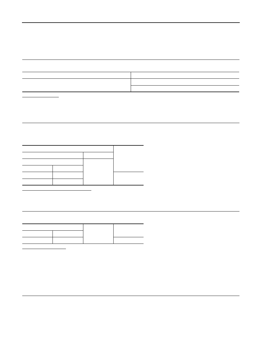
Test item
Operation
Description
CORNERING LAMP
Off
NOTE:
The item is indicated, but cannot be tested.
LH
RH
HORN
On
Operates horn relay 1 and horn relay 2 for 20 ms.
FRONT WIPER
Off
OFF
Lo
Operates the front wiper relay.
Hi
Operates the front wiper relay and front wiper high relay.
MOTOR FAN
1
OFF
2
Outputs 50% pulse duty signal (PWM signal) to the cooling fan control module.
3
Outputs 80% pulse duty signal (PWM signal) to the cooling fan control module.
4
Outputs 100% pulse duty signal (PWM signal) to the cooling fan control module.

WW-24
< SYSTEM DESCRIPTION >
DIAGNOSIS SYSTEM (IPDM E/R)
HEAD LAMP WASHER
On
NOTE:
The item is indicated, but cannot be tested.
EXTERNAL LAMPS
Off
OFF
TAIL
Operates the tail lamp relay.
Lo
Operates the headlamp low relay.
Hi
Operates the headlamp low relay and ON/OFF the headlamp high relay at 1 sec-
ond intervals.
Fog
Operates the front fog lamp relay.
Test item
Operation
Description
WIPER AND WASHER FUSE
WW-25
< DTC/CIRCUIT DIAGNOSIS >
C
D
E
F
G
H
I
J
K
M
A
B
WW
N
O
P
DTC/CIRCUIT DIAGNOSIS
WIPER AND WASHER FUSE
Description
INFOID:0000000005234750
Fuse list
Diagnosis Procedure
INFOID:0000000005234751
1.
CHECK FUSES
Check that the following fuses are not fusing.
Is the fuse fusing?
YES
>> Replace the fuse with a new one after repairing the applicable circuit.
NO
>> The fuse is normal.
Unit
Location
No.
Capacity
Front wiper motor
IPDM E/R
60
30 A
Washer pump
IPDM E/R
47
10 A
Unit
Location
No.
Capacity
Front wiper motor
IPDM E/R
60
30 A
Washer pump
IPDM E/R
47
10 A
WW-26
< DTC/CIRCUIT DIAGNOSIS >
POWER SUPPLY AND GROUND CIRCUIT
POWER SUPPLY AND GROUND CIRCUIT
BCM (BODY CONTROL MODULE)
BCM (BODY CONTROL MODULE) : Diagnosis Procedure
INFOID:0000000005234752
1.
CHECK FUSE AND FUSIBLE LINK
Check that the following fuse and fusible link are not blown.
Is the fuse fusing?
YES
>> Replace the blown fuse or fusible link after repairing the affected circuit if a fuse or fusible link is
blown.
NO
>> GO TO 2.
2.
CHECK POWER SUPPLY CIRCUIT
1.
Turn ignition switch OFF.
2.
Disconnect BCM connectors.
3.
Check voltage between BCM harness connector and ground.
Is the measurement value normal?
YES
>> GO TO 3.
NO
>> Repair harness or connector.
3.
CHECK GROUND CIRCUIT
Check continuity between BCM harness connector and ground.
Does continuity exist?
YES
>> INSPECTION END
NO
>> Repair harness or connector.
IPDM E/R (INTELLIGENT POWER DISTRIBUTION MODULE ENGINE ROOM)
IPDM E/R (INTELLIGENT POWER DISTRIBUTION MODULE ENGINE ROOM) : Di-
agnosis Procedure
INFOID:0000000005234753
1.
CHECK FUSES AND FUSIBLE LINK
Check that the following IPDM E/R fuses or fusible links are not blown.
Signal name
Fuse and fusible link No.
Battery power supply
L
10
Terminals
Voltage
(Approx.)
(+)
(
−
)
BCM
Ground
Connector
Terminal
M118
1
Battery voltage
M119
11
BCM
Ground
Continuity
Connector
Terminal
M119
13
Existed
Нет комментариевНе стесняйтесь поделиться с нами вашим ценным мнением.
Текст