Infiniti FX35, FX50 (S51). Manual — part 1012

EXL-44
< DTC/CIRCUIT DIAGNOSIS >
[XENON TYPE]
B2503, B2504 SWIVEL ACTUATOR
DTC/CIRCUIT DIAGNOSIS
B2503, B2504 SWIVEL ACTUATOR
Description
INFOID:0000000005244694
SWIVEL ACTUATOR
The swivel actuator is installed in the headlamp unit. The swivel actuator consists of the swivel motor and the
swivel position sensor.
SWIVEL MOTOR
• The swivel motor is the two-phase step motor.
• The swivel motor drives headlamp by exciting the two drive coils according to the drive signal from AFS con-
trol unit.
• The rotation direction of the swivel motor is changeable by changing the exciting pattern.
SWIVEL POSITION SENSOR
The swivel position sensor detects the headlamp swivel angle to transmit the swivel position sensor signal to
AFS control unit.
DTC Logic
INFOID:0000000005244695
DTC DETECTION LOGIC
• [B2503] Swivel actuator [RH]
• [B2504] Swivel actuator [LH]
*: initialization is not included.
DTC CONFIRMATION PROCEDURE
1.
DTC ERASE
Erase the DTC memory of AFS with CONSULT-III.
>> GO TO 2.
2.
CONFIRMATION DTC SELECTION
Select "B2503" or "B2504" for confirmation.
Which DTC is confirmation?
B2503 >> GO TO 3.
B2504 >> GO TO 4.
3.
DTC CONFIRMATION (B2503)
1.
Steer to the straight-forward position.
2.
Start the engine.
3.
Turn the headlamp ON.
4.
Shift the selector lever to "N".
5.
Steer to the right. (Rotate it once or more.)
6.
Perform the self-diagnosis with CONSULT-III.
DTC detection condition
DTC erase
condition
Possible cause
AFS control unit indicates an applicable DTC when detecting any of the follow-
ing conditions continuously for 2 seconds or more.
• AFS control unit-recognized swivel position differs extremely from the swivel
position sensor-input value while the swivel operating.
*
• The swivel position sensor signal does not change even though AFS control
unit transmits the swivel motor driving signal while the swivel operating
*
.
• The swivel motor short and open is detected while the swivel operating
*
.
• The swivel position sensor power supply is 6 V or more, or 4 V or less.
• The swivel position sensor signal is 0.25 V or less, or 4.75 V or more.
Ignition switch
OFF
Swivel position sensor
• Swivel position sensor
• Harness and connector
• AFS control unit
Swivel motor
• Swivel motor
• Harness and connector
• AFS control unit

B2503, B2504 SWIVEL ACTUATOR
EXL-45
< DTC/CIRCUIT DIAGNOSIS >
[XENON TYPE]
C
D
E
F
G
H
I
J
K
M
A
B
EXL
N
O
P
Is "B2503" detected?
YES
>> Refer to
.
NO
>> Refer to
GI-36, "Intermittent Incident"
.
4.
DTC CONFIRMATION (B2504)
1.
Steer to the straight-forward position.
2.
Start the engine.
3.
Turn the headlamp ON.
4.
Drive at 25 km/h (15.5 MPH) or more.
5.
Steer to the left. (Rotate it once or more.)
6.
Stop the vehicle.
7.
Perform the self-diagnosis with CONSULT-III.
Is "B2504" detected?
YES
>> Refer to
.
NO
>> Refer to
GI-36, "Intermittent Incident"
.
Diagnosis Procedure
INFOID:0000000005244696
1.
CHECK SWIVEL POSITION SENSOR SIGNAL INPUT
1.
Turn the ignition switch ON.
2.
Check the voltage between the AFS control unit harness connector and the ground.
Is the measurement value within the standard value?
YES
>> GO TO 2.
Less than the standard value >>GO TO 6.
Higher than the standard value>>GO TO 9.
2.
CHECK SWIVEL MOTOR
Check the swivel motor.
EXL-48, "Component Inspection"
.
Is the inspection result normal?
YES
>> GO TO 3.
NO
>> Replace the front combination lamp.
3.
CHECK SWIVEL MOTOR OPEN CIRCUIT
1.
Turn the ignition switch OFF.
2.
Disconnect AFS control unit connector and the headlamp swivel actuator connector.
3.
Check continuity between the AFS control unit harness connector and the headlamp swivel actuator har-
ness connector.
Terminals
Voltage
(Approx.)
(+)
(
−
)
AFS control unit
Ground
Connector
Terminal
RH
M16
9
0.25 - 4.75 V
LH
29

EXL-46
< DTC/CIRCUIT DIAGNOSIS >
[XENON TYPE]
B2503, B2504 SWIVEL ACTUATOR
Does continuity exist?
YES
>> GO TO 4.
NO
>> Repair the harnesses or connectors.
4.
CHECK SWIVEL MOTOR SHORT CIRCUIT
Check continuity between the AFS control unit harness connector and the ground.
Does continuity exist?
YES
>> Repair the harnesses or connectors.
NO
>> GO TO 5.
5.
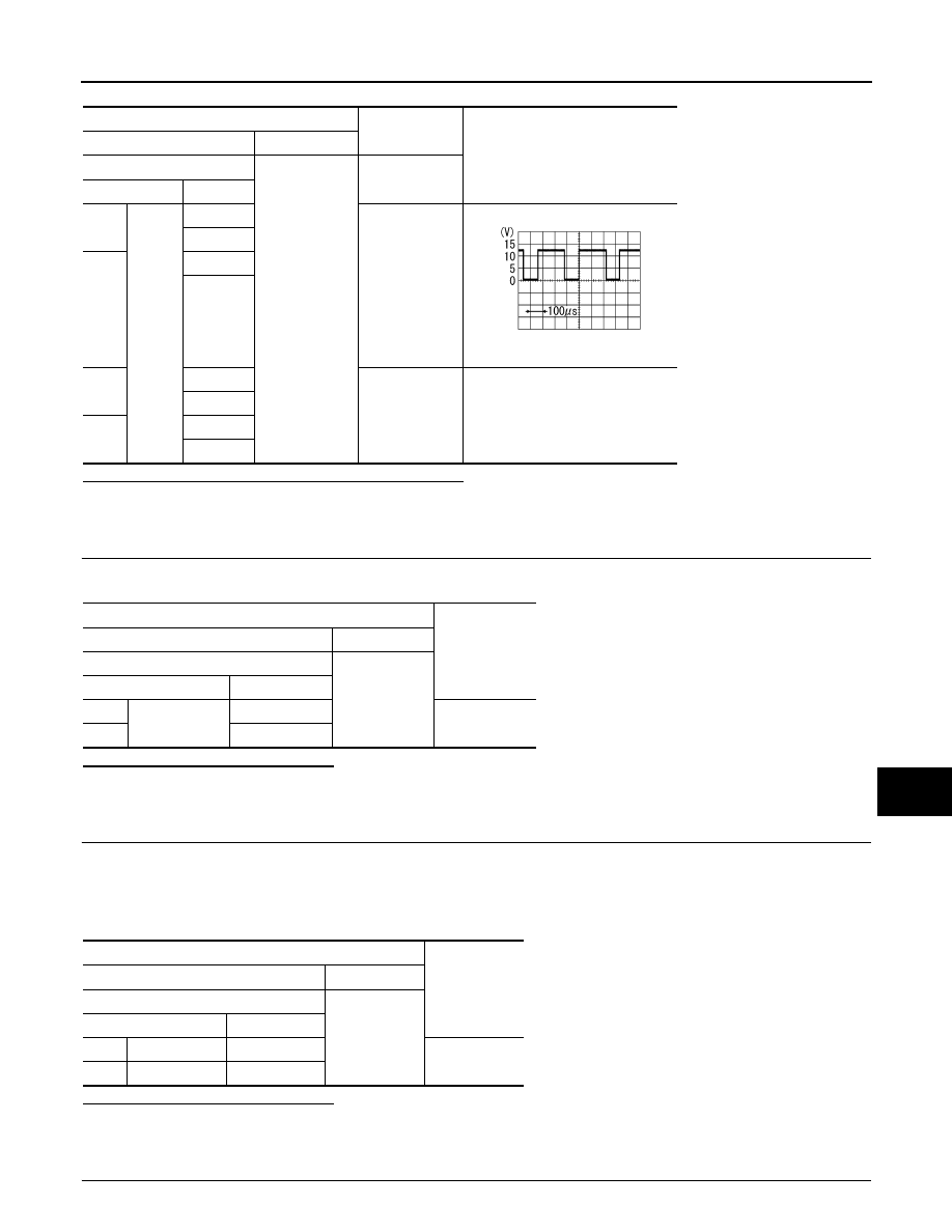
CHECK SWIVEL MOTOR CIRCUIT VOLTAGE OUTPUT
1.
Connect AFS control unit connector.
2.
Turn the ignition switch ON.
3.
Turn the headlamp ON.
4.
Select “LOW BEAM TEST RIGHT” or LOW BEAM TEST LEFT“” of ADAPTIVE LIGHT active test item.
5.
With operating the test item, check the voltage between the AFS control unit harness connector and the
ground.
AFS control unit
Headlamp swivel
actuator
Continuity
Connector
Terminal
Connector
Terminal
RH
M16
11
E29
8
Existed
13
7
32
3
34
4
LH
15
E59
3
17
4
36
8
38
7
AFS control unit
Ground
Continuity
Connector
Terminal
RH
M16
11
Not existed
13
32
34
LH
15
17
36
38
B2503, B2504 SWIVEL ACTUATOR
EXL-47
< DTC/CIRCUIT DIAGNOSIS >
[XENON TYPE]
C
D
E
F
G
H
I
J
K
M
A
B
EXL
N
O
P
Is the measurement value within the standard value?
YES
>> Replace the front combination lamp.
NO
>> Replace AFS control unit.
6.
CHECK SWIVEL POSITION SENSOR SIGNAL OUTPUT
Check the voltage between the AFS control unit harness connector and the ground.
Is the measurement value normal?
YES
>> GO TO 7.
NO
>> GO TO 9.
7.
CHECK SWIVEL POSITION SENSOR POWER SUPPLY CIRCUIT INPUT VOLTAGE
1.
Turn the ignition switch OFF.
2.
Disconnect the headlamp swivel actuator connector.
3.
Turn the ignition switch ON.
4.
Check the voltage between the headlamp swivel actuator harness connector and the ground.
Is the measurement value normal?
YES
>> GO TO 8.
NO
>> Repair the harnesses or connectors.
8.
CHECK SWIVEL POSITION SENSOR SIGNAL SHORT CIRCUIT
Terminals
Condition
Voltage
(Approx.)
(+)
(
−
)
AFS control unit
Ground
Swivel motor
Connector
Terminal
RH
M16
11
Active
8 - 12 V
32
LH
15
36
RH
13
Stop
9.5 - 11.5 V
34
LH
17
38
SKIB2408J
Terminals
Voltage
(Approx.)
(+)
(
−
)
AFS control unit
Ground
Connector
Terminal
RH
M16
4
5 V
LH
24
Terminals
Voltage
(Approx.)
(+)
(
−
)
Headlamp swivel actuator
Ground
Connector
Terminal
RH
E29
2
5 V
LH
E59
2
Нет комментариевНе стесняйтесь поделиться с нами вашим ценным мнением.
Текст