Infiniti FX35, FX50 (S51). Manual — part 498
HALF LATCH SWITCH
DLK-115
< DTC/CIRCUIT DIAGNOSIS >
C
D
E
F
G
H
I
J
L
M
A
B
DLK
N
O
P
HALF LATCH SWITCH
Description
INFOID:0000000005239630
The half latch switch is integrated in the back door lock assembly and it detects the half latch condition of the
back door lock.
Diagnosis Procedure
INFOID:0000000005239631
1.
CHECK BACK DOOR CONTROL UNIT OUTPUT
1.
Turn ignition switch OFF.
2.
Disconnect back door lock assembly connector.
3.
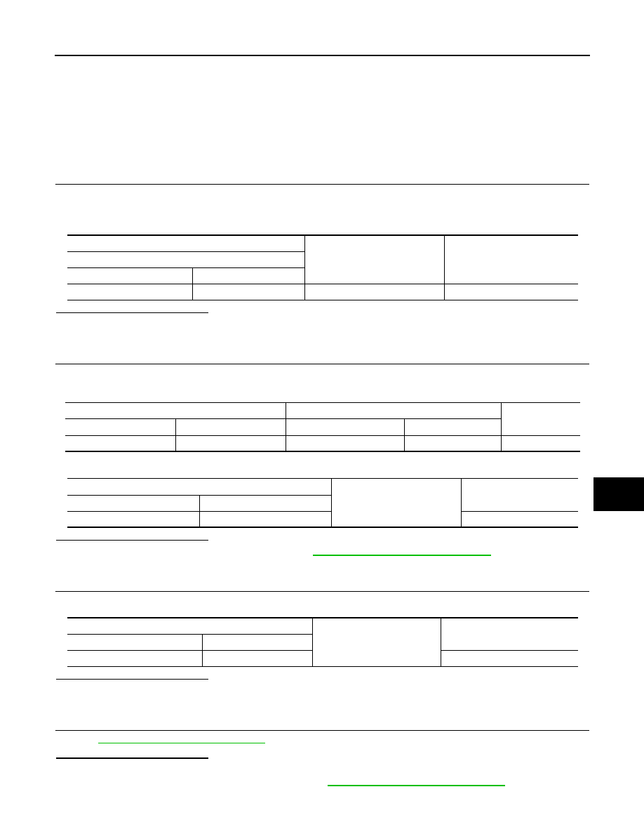
Check voltage between back door lock assembly harness connector and ground.
Is the inspection result normal?
YES
>> GO TO 3.
NO
>> GO TO 2.
2.
CHECK HALF LATCH SWITCH CIRCUIT
1.
Disconnect back door control unit connector.
2.
Check continuity between back door control unit harness connector.
3.
Check continuity between back door control unit harness connector and ground.
Is the inspection result normal?
YES
>> Replace back door control unit. Refer to
DLK-285, "Removal and Installation"
NO
>> Repair or replace harness.
3.
CHECK HALF LATCH SWITCH GROUND CIRCUIT
Check continuity between back door lock assembly harness connector and ground.
Is the inspection result normal?
YES
>> GO TO 4.
NO
>> Repair or replace harness.
4.
CHECK HALF LATCH SWITCH
DLK-116, "Component Inspection"
.
Is the inspection result normal?
YES
>> GO TO 5.
NO
>> Replace back door lock assembly. Refer to
DLK-277, "Removal and Installation"
.
(–)
(–)
Voltage (V)
(Approx.)
Half latch switch
Connector
Terminal
D122
6
Ground
Battery voltage
Back door control unit
Back door lock assembly
Continuity
Connector
Terminal
Connector
Terminal
D123
2
D122
6
Existed
Back door control unit
Ground
Continuity
Connector
Terminal
D123
2
Not existed
Back door lock assembly
Ground
Continuity
Connector
Terminal
D122
8
Existed
DLK-116
< DTC/CIRCUIT DIAGNOSIS >
HALF LATCH SWITCH
5.
CHECK INTERMITTENT INCIDENT
GI-36, "Intermittent Incident"
>> INSPECTION END
Component Inspection
INFOID:0000000005239632
COMPONENT INSPECTION
1.
CHECK HALF LATCH SWITCH
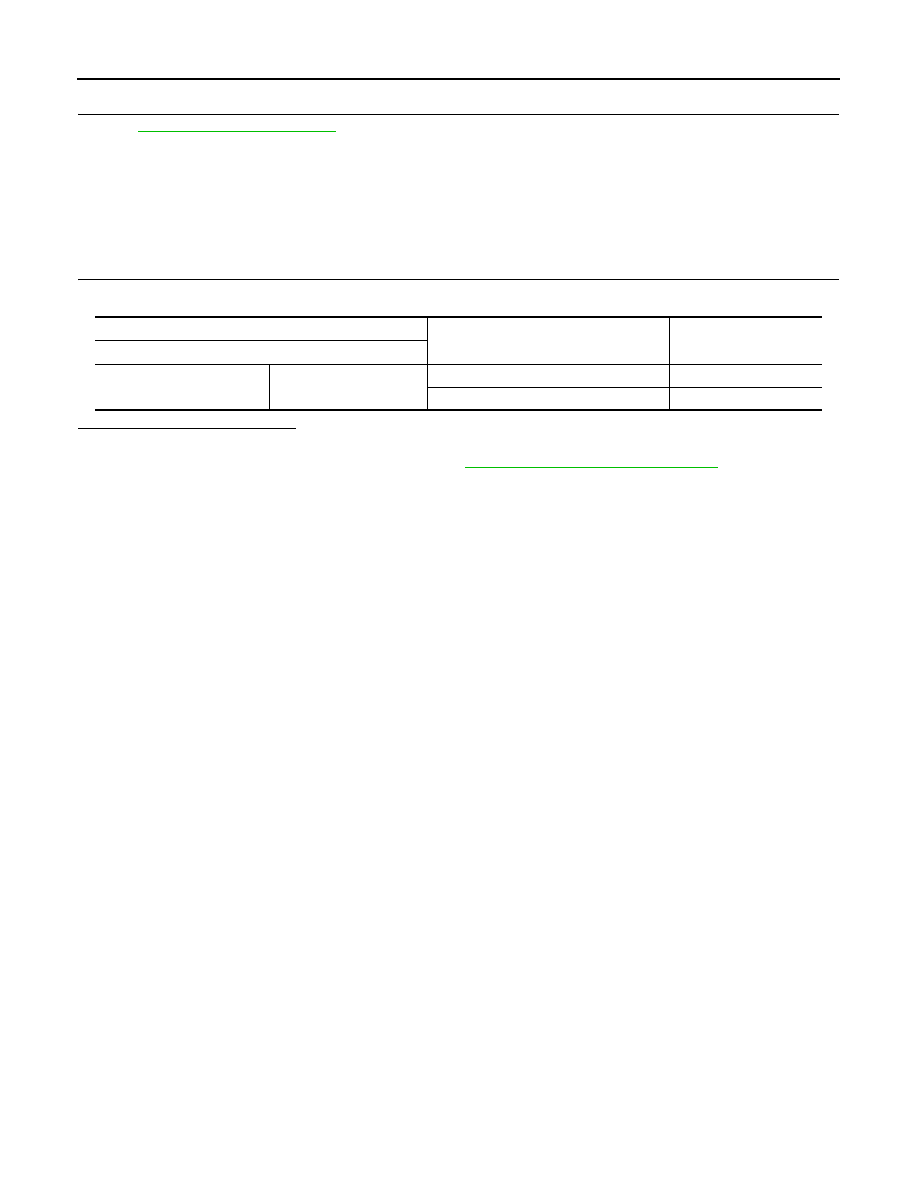
Check back door lock assembly (half latch switch).
Is the inspection result normal?
YES
>> INSPECTION END
NO
>> Replace back door lock assembly. Refer to
DLK-277, "Removal and Installation"
.
Terminal
Back door lock position
Continuity
Back door lock assembly (half latch switch) connector
6
8
Open
Existed
Fully closed/Half latch
Not existed
BACK DOOR CLOSURE MOTOR
DLK-117
< DTC/CIRCUIT DIAGNOSIS >
C
D
E
F
G
H
I
J
L
M
A
B
DLK
N
O
P
BACK DOOR CLOSURE MOTOR
Description
INFOID:0000000005239633
The back door lock assembly consists of the open switch, close switch, half latch switch and closure motor.
The back door control unit determines the back door lock condition according to the signal from each switch
and performs the open/close operation of closure motor.
Diagnosis Procedure
INFOID:0000000005239634
1.
CHECK BACK DOOR CLOSURE MOTOR CIRCUIT
1.
Turn ignition switch OFF.
2.
Disconnect back door control unit connector and back door lock assembly connector.
3.
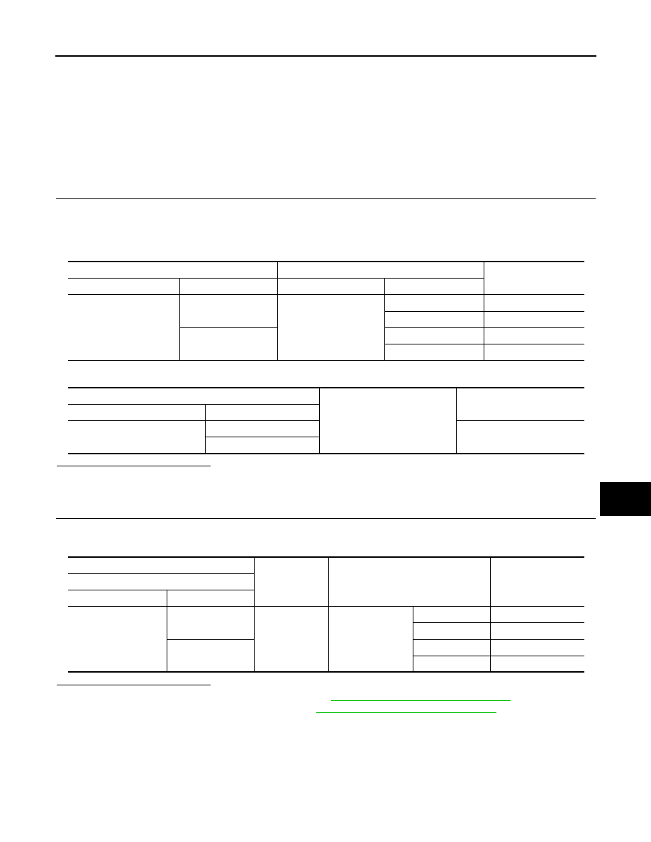
Check continuity between back door control unit harness connector and back door lock assembly harness
connector.
4.
Check continuity between back door control unit harness connector and ground.
Is the inspection result normal?
YES
>> GO TO 2.
NO
>> Repair or replace harness.
2.
CHECK BACK DOOR CLOSURE MOTOR CIRCUIT
1.
Connect back door control unit connector and back door lock assembly connector.
2.
Check voltage between back door unit harness connector and ground.
Is the inspection result normal?
YES
>> Replace back door lock assembly. Refer to
DLK-277, "Removal and Installation"
.
NO
>> Replace back door control unit. Refer to
DLK-285, "Removal and Installation"
Back door control unit
Back door lock assembly
Continuity
Connector
Terminal
Connector
Terminal
D123
4
D122
1
Not existed
2
Existed
10
1
Existed
2
Not existed
Back door control unit
Ground
Continuity
Connector
Terminal
D123
4
Not existed
10
(+)
(–)
Condition
Voltage (V)
(Approx.)
Back door control unit
Connector
Terminal
D123
4
Ground
Back door closure
Close operation
Battery voltage
Other than above
0
10
Open operation
Battery voltage
Other than above
0

DLK-118
< DTC/CIRCUIT DIAGNOSIS >
INTEGRATED HOMELINK TRANSMITTER
INTEGRATED HOMELINK TRANSMITTER
Description
INFOID:0000000005239635
Integrated Homelink Transmitter can store and transmit a maximum of 3 radio signals.
Allows operation of garage doors, gates, home and office lighting, entry door locks and security system, etc.
Integrated Homelink Transmitter power supply uses vehicle battery, which enables it to maintain every pro-
gram in case battery is discharged or removed.
Component Function Check
INFOID:0000000005239636
1.
CHECK FUNCTION
Check that system receiver (garage door opener, etc.) operates with original hand-held transmitter.
Is the inspection result normal?
YES
>> GO TO 2.
NO
>> Receiver or hand-held transmitter is malfunctioning.
2.
CHECK ILLUMINATE
1.
Turn ignition switch OFF.
2.
Does red light of transmitter illuminate when any transmitter button is pressed?
Is the inspection result normal?
YES
>> GO TO 3.
NO
>> Refer to
DLK-118, "Diagnosis Procedure"
3.
CHECK TRANSMITTER
Check transmitter with Tool*.
*:For details, refer to Technical Service Bulletin.
Is the inspection result normal?
YES
>> Receiver or hand-held transmitter malfunction, not vehicle related.
NO
>> Replace auto anti-dazzling inside mirror (homelink universal transceiver). Refer to
(with ADP) or
MIR-99, "Removal and Installation"
(Without ADP).
Diagnosis Procedure
INFOID:0000000005239637
1.
CHECK POWER SUPPLY
1.
Turn ignition switch OFF.
2.
Disconnect auto anti-dazzling inside mirror (homelink universal transceiver) connector.
3.
Check voltage between auto anti-dazzling inside mirror (home link universal transceiver) harness connec-
tor and ground.
Is the inspection result normal?
YES
>> GO TO 2.
NO
>>
Check the following items.
• 10A fuse [No. 3 located in the fuse block (J/B)]
• 10A fuse [No. 6 located in the fuse block (J/B)]
• Harness for open or short between fuse and auto anti-dazzling inside mirror (homelink universal
transceiver).
2.
CHECK GROUND CIRCUIT
Check continuity between auto anti-dazzling inside mirror (homelink universal transceiver) harness connector
and ground.
Auto anti-dazzling inside mirror
(Homelink universal transceiver)
connector
Terminal Condition
Voltage (V)
(Approx.)
R3
10
Ground
Ignition switch position:
OFF
Battery voltage
6
Ignition switch position:
ON
Нет комментариевНе стесняйтесь поделиться с нами вашим ценным мнением.
Текст