Infiniti FX35, FX50 (S51). Manual — part 1900
WCS-20
< DTC/CIRCUIT DIAGNOSIS >
POWER SUPPLY AND GROUND CIRCUIT
DTC/CIRCUIT DIAGNOSIS
POWER SUPPLY AND GROUND CIRCUIT
COMBINATION METER
COMBINATION METER : Diagnosis Procedure
INFOID:0000000005524753
1.
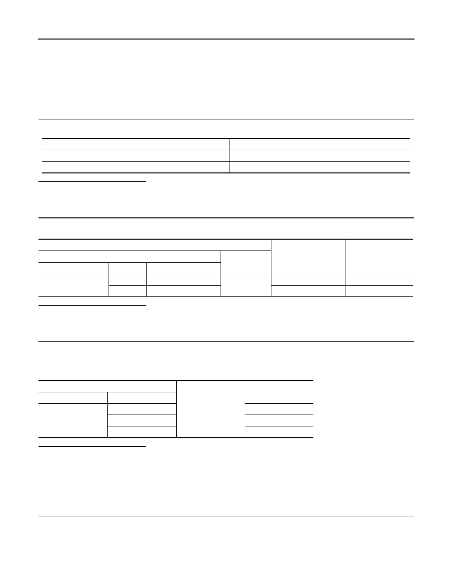
CHECK FUSE
Check for blown fuses.
Is the inspection result normal?
YES
>> GO TO 2.
NO
>> Be sure to eliminate cause of malfunction before installing new fuse.
2.
CHECK POWER SUPPLY CIRCUIT
Check voltage between combination meter harness connector and ground.
Is the inspection result normal?
YES
>> GO TO 3.
NO
>> Check harness between combination meter and fuse.
3.
CHECK GROUND CIRCUIT
1.
Turn ignition switch OFF.
2.
Disconnect combination meter connector.
3.
Check continuity between combination meter harness connector and ground.
Is the inspection result normal?
YES
>> INSPECTION END
NO
>> Repair harness or connector.
UNIFIED METER AND A/C AMP.
UNIFIED METER AND A/C AMP. : Diagnosis Procedure
INFOID:0000000005524754
1.
CHECK FUSE
Check for blown fuses.
Power source
Fuse No.
Battery
11
Ignition switch ON or START
4
Terminals
Ignition switch position
Value (Approx.)
(+)
(-)
Combination meter
Terminal
Signal name
M53
1
Battery power supply
Ground
OFF
Battery voltage
21
Ignition signal
ON
Battery voltage
Combination meter
Ground
Continuity
Connector
Terminal
M53
5
Existed
15
Existed
22
Existed

WCS
POWER SUPPLY AND GROUND CIRCUIT
WCS-21
< DTC/CIRCUIT DIAGNOSIS >
C
D
E
F
G
H
I
J
K
L
M
B
A
O
P
Is the inspection result normal?
YES
>> GO TO 2.
NO
>> Be sure to eliminate cause of malfunction before installing new fuse.
2.
CHECK POWER SUPPLY CIRCUIT
Check voltage between unified meter and A/C amp. harness connector and ground.
Is the inspection result normal?
YES
>> GO TO 3.
NO
>> Check harness between unified meter and A/C amp. and fuse.
3.
CHECK GROUND CIRCUIT
1.
Turn ignition switch OFF.
2.
Disconnect unified meter and A/C amp. connector.
3.
Check continuity between unified meter and A/C amp. harness connector and ground.
Is the inspection result normal?
YES
>> INSPECTION END
NO
>> Repair harness or connector.
BCM (BODY CONTROL MODULE)
BCM (BODY CONTROL MODULE) : Diagnosis Procedure
INFOID:0000000005619281
1.
CHECK FUSE AND FUSIBLE LINK
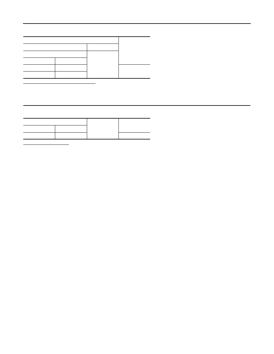
Check that the following fuse and fusible link are not blown.
Is the fuse fusing?
YES
>> Replace the blown fuse or fusible link after repairing the affected circuit if a fuse or fusible link is
blown.
NO
>> GO TO 2.
2.
CHECK POWER SUPPLY CIRCUIT
1.
Turn ignition switch OFF.
2.
Disconnect BCM connectors.
Power source
Fuse No.
Battery
11
Ignition switch ACC or ON
19
Ignition switch ON or START
3
Terminals
Ignition switch position
Value (Approx.)
(+)
(-)
Unified meter A/C amp.
Terminal
Signal name
M67
54
Battery power supply
Ground
OFF
Battery voltage
41
ACC power supply
ACC
Battery voltage
53
Ignition signal
ON
Battery voltage
Unified meter A/C amp.
Ground
Continuity
Connector
Terminal
M67
55
Existed
71
Existed
Signal name
Fuse and fusible link No.
Battery power supply
L
10
WCS-22
< DTC/CIRCUIT DIAGNOSIS >
POWER SUPPLY AND GROUND CIRCUIT
3.
Check voltage between BCM harness connector and ground.
Is the measurement value normal?
YES
>> GO TO 3.
NO
>> Repair harness or connector.
3.
CHECK GROUND CIRCUIT
Check continuity between BCM harness connector and ground.
Does continuity exist?
YES
>> INSPECTION END
NO
>> Repair harness or connector.
Terminals
Voltage
(Approx.)
(+)
(
−
)
BCM
Ground
Connector
Terminal
M118
1
Battery voltage
M119
11
BCM
Ground
Continuity
Connector
Terminal
M119
13
Existed

WCS
METER BUZZER CIRCUIT
WCS-23
< DTC/CIRCUIT DIAGNOSIS >
C
D
E
F
G
H
I
J
K
L
M
B
A
O
P
METER BUZZER CIRCUIT
Description
INFOID:0000000005524721
• The buzzer for warning chime system is installed in the combination meter.
• The combination meter sounds the alarm buzzer based on the signals transmitted from various units.
Component Function Check
INFOID:0000000005524722
1.
CHECK OPERATION OF METER BUZZER
1.
Select “BUZZER” of “BCM” on CONSULT-III.
2.
Perform “LIGHT WARN ALM” of “ACTIVE TEST”.
Does meter buzzer beep?
YES
>> INSPECTION END
NO
>> GO TO 2.
2.
CHECK UNIFIED METER AND A/C AMP. INPUT SIGNAL
Select the “Data Monitor” for the “METER/M&A” and check the “BUZZER” monitor value.
Is the inspection result normal?
YES
>> Replace combination meter.
NO
>> Replace BCM. Refer to
BCS-83, "Removal and Installation"
Diagnosis Procedure
INFOID:0000000005524723
1.
CHECK POWER SUPPLY OF COMBINATION METER
Check power supply of combination meter. Refer to
WCS-20, "COMBINATION METER : Diagnosis Proce-
.
Is the inspection result normal?
YES
>> GO TO 2.
NO
>> Repair power supply circuit of combination meter.
2.
CHECK POWER SUPPLY OF UNIFIED METER AND A/C AMP.
Check power supply of unified meter and A/C amp. Refer to
MWI-58, "COMBINATION METER : Diagnosis
.
Is the inspection result normal?
YES
>> INSPECTION END
NO
>> Repair power supply circuit of unified meter and A/C amp.
BUZZER
Under the condition of buzzer input
: On
Except above
: Off
Нет комментариевНе стесняйтесь поделиться с нами вашим ценным мнением.
Текст