Infiniti FX35, FX50 (S51). Manual — part 770
AIR CONDITIONING CUT CONTROL
EC-621
< SYSTEM DESCRIPTION >
[VK50VE]
C
D
E
F
G
H
I
J
K
L
M
A
EC
N
P
O
AIR CONDITIONING CUT CONTROL
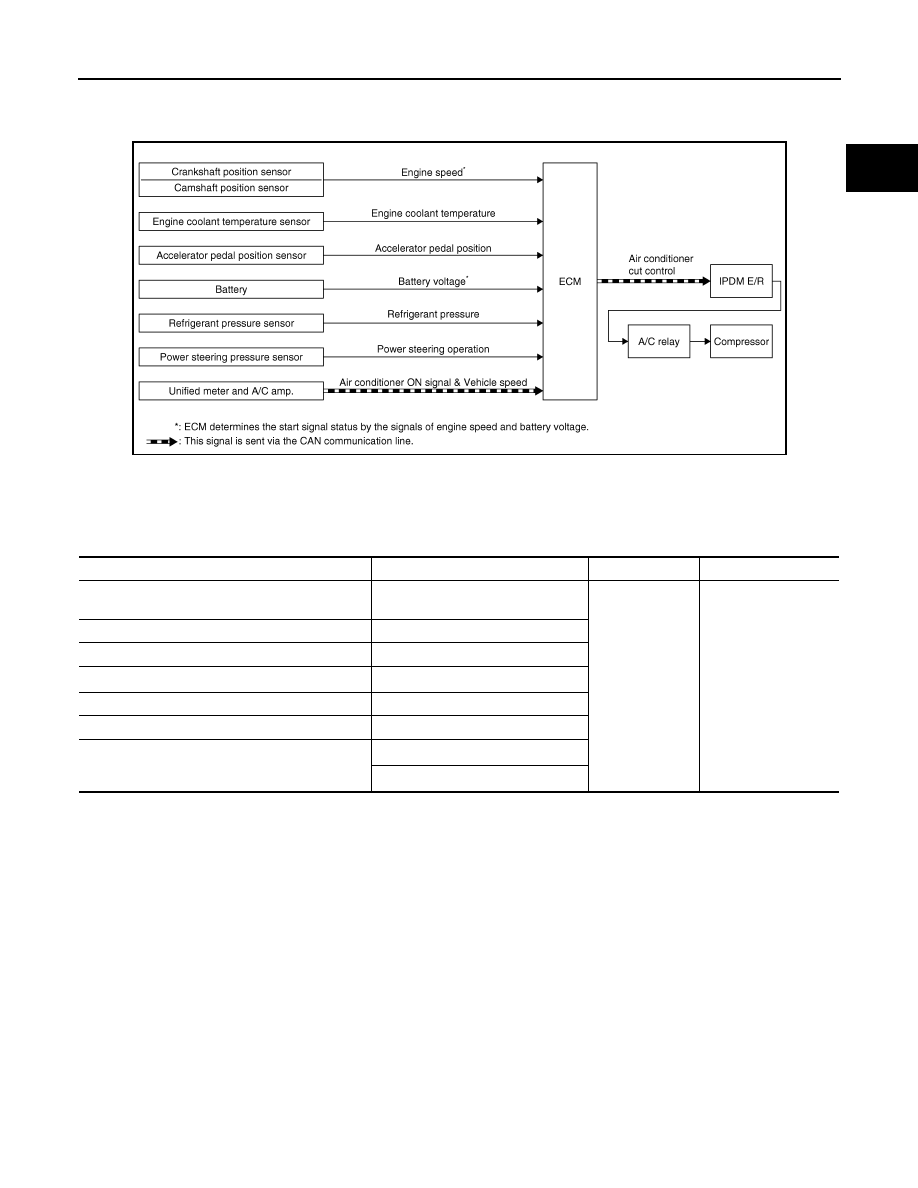
System Diagram
INFOID:0000000005237180
System Description
INFOID:0000000005237181
INPUT/OUTPUT SIGNAL CHART
*1: This signal is sent to the ECM via the CAN communication line.
*2: ECM determines the start signal status by the signals of engine speed and battery voltage.
SYSTEM DESCRIPTION
This system improves engine operation when the air conditioner is used.
Under the following conditions, the air conditioner is turned off.
• When the accelerator pedal is fully depressed.
• When cranking the engine.
• At high engine speeds.
• When the engine coolant temperature becomes excessively high.
• When operating power steering during low engine speed or low vehicle speed.
• When engine speed is excessively low.
• When refrigerant pressure is excessively low or high.
JMBIA1528GB
Sensor
Input signal to ECM
ECM function
Actuator
Crankshaft position sensor
Camshaft position sensor
Engine speed*
2
Air conditioner
cut control
IPDM E/R
↓
A/C relay
↓
Compressor
Engine coolant temperature sensor
Engine coolant temperature
Accelerator pedal position sensor
Accelerator pedal position
Battery
Battery voltage*
2
Refrigerant pressure sensor
Refrigerant pressure
Power steering pressure sensor
Power steering operation
Unified meter and A/C amp.
Air conditioner ON signal*
1
Vehicle speed*
1

EC-622
< SYSTEM DESCRIPTION >
[VK50VE]
AIR CONDITIONING CUT CONTROL
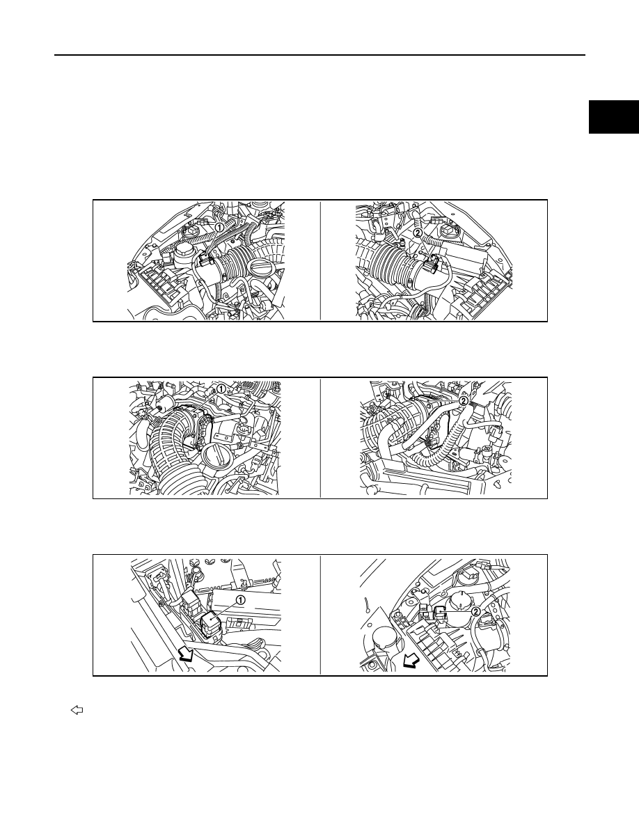
Component Parts Location
INFOID:0000000005589021
1.
IPDM E/R
2.
VVEL control module
3.
Battery current sensor
4.
VVEL actuator motor relay
5.
Cooling fan relay-1
6.
Cooling fan relay-2
7.
Mass air flow sensor (bank 2)
8.
Refrigerant pressure sensor
9.
Exhaust valve timing control position
sensor (bank 2)
10. Exhaust valve timing control sole-
noid valve (bank 2)
11.
Camshaft position sensor (bank 2)
12. Intake valve timing control solenoid
valve (bank 2)
13. Cooling fan motor-1
14. Cooling fan control module-1
15. Cooling fan motor-2
16. Cooling fan control module-2
17. Intake valve timing control solenoid
valve (bank 1)
18. Camshaft position sensor (bank 1)
19. Exhaust valve timing control sole-
noid valve (bank 1)
20. Exhaust valve timing control position
sensor (bank 1)
21. Mass air flow sensor (with intake air
temperature sensor) (bank 1)
22. ICC brake hold relay (ICC models)
23. Brake booster pressure sensor
24. Ignition coil (with power transistor)
and spark plug (bank 1)
25. VVEL actuator motor (bank 1)
26. VVEL control shaft position sensor
(bank 1)
27. Fuel injector (bank 1)
28. Electric throttle control actuator
(bank 1)
29. A/F sensor 1 (bank 1)
30. Knock sensor (bank 1)
JMBIA1535ZZ
AIR CONDITIONING CUT CONTROL
EC-623
< SYSTEM DESCRIPTION >
[VK50VE]
C
D
E
F
G
H
I
J
K
L
M
A
EC
N
P
O
31. EVAP canister purge volume con-
trol solenoid valve
32. Manifold Absolute Pressure Sensor
(This sensor is not for controlling the
engine system, nor for the on board
diagnosis.)
33. Knock sensor (bank 2)
34. Crankshaft position sensor
35. Electric throttle control actuator
(bank2)
36. VVEL actuator motor (bank 2)
37. VVEL control shaft position sensor
(bank 2)
38. A/F sensor 1 (bank 2)
39. Engine coolant temperature sensor
40. Fuel injector (bank 2)
41. EVAP service port
42. Ignition coil (with power transistor)
and spark plug (bank 2)
1.
Mass air flow sensor (bank 2)
2.
Mass air flow sensor (with intake air
temperature sensor) (bank 1)
1.
Electric throttle control actuator
(bank 2)
2.
Electric throttle control actuator
(bank 1)
1.
Cooling fan relay-1
2.
Cooling fan relay-2
Vehicle front
JMBIA1536ZZ
JMBIA1537ZZ
JMBIA1538ZZ
EC-624
< SYSTEM DESCRIPTION >
[VK50VE]
AIR CONDITIONING CUT CONTROL
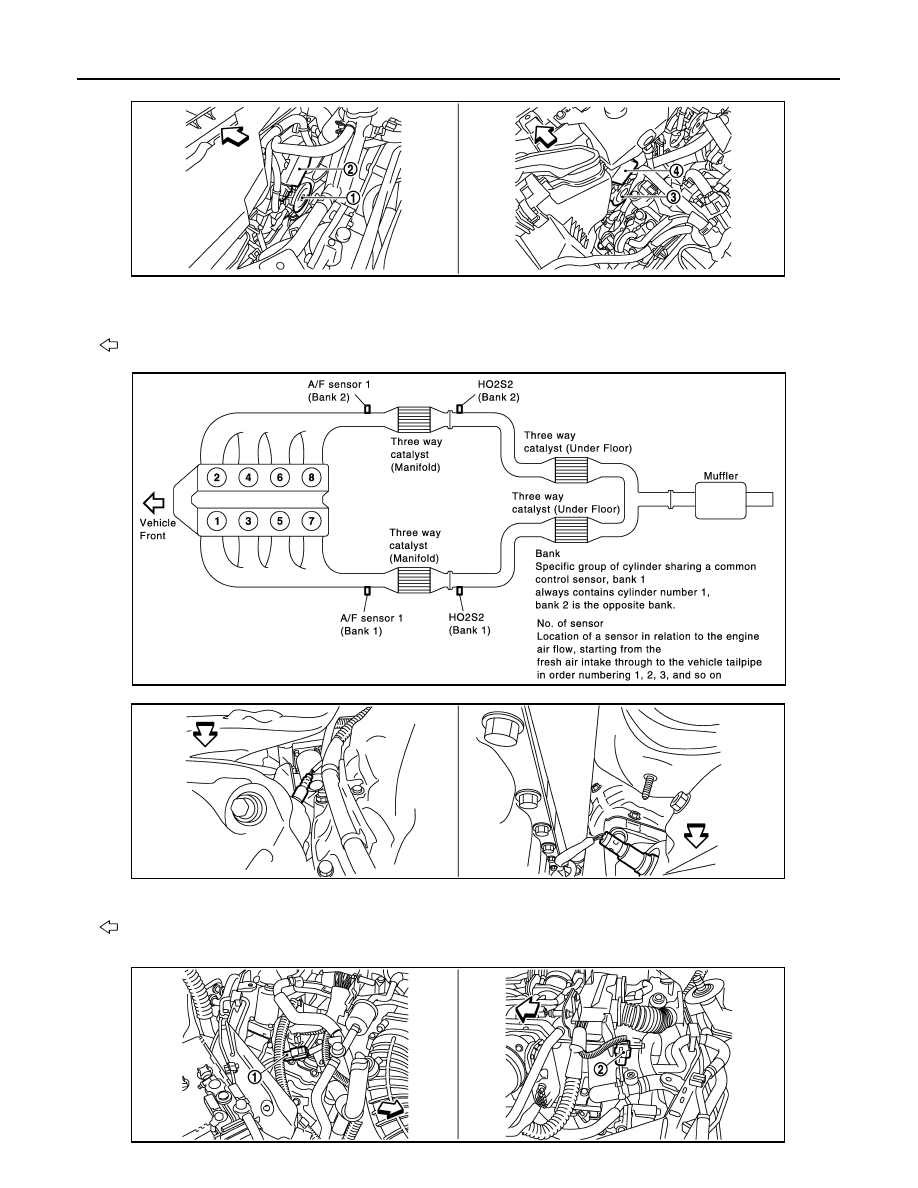
1.
Cooling fan motor-1
2.
Cooling fan control module-1
3.
Cooling fan motor-2
4.
Cooling fan control module-2
Vehicle front
JMBIA1539ZZ
JMBIA1576GB
1.
A/F sensor 1 (bank 1)
2.
A/F sensor 1 (bank 2)
Vehicle front
JMBIA1540ZZ
JMBIA1541ZZ
Нет комментариевНе стесняйтесь поделиться с нами вашим ценным мнением.
Текст