Infiniti FX35, FX50 (S51). Manual — part 786
INTAKE VALVE TIMING CONTROL
EC-685
< SYSTEM DESCRIPTION >
[VK50VE]
C
D
E
F
G
H
I
J
K
L
M
A
EC
N
P
O
INTAKE VALVE TIMING CONTROL
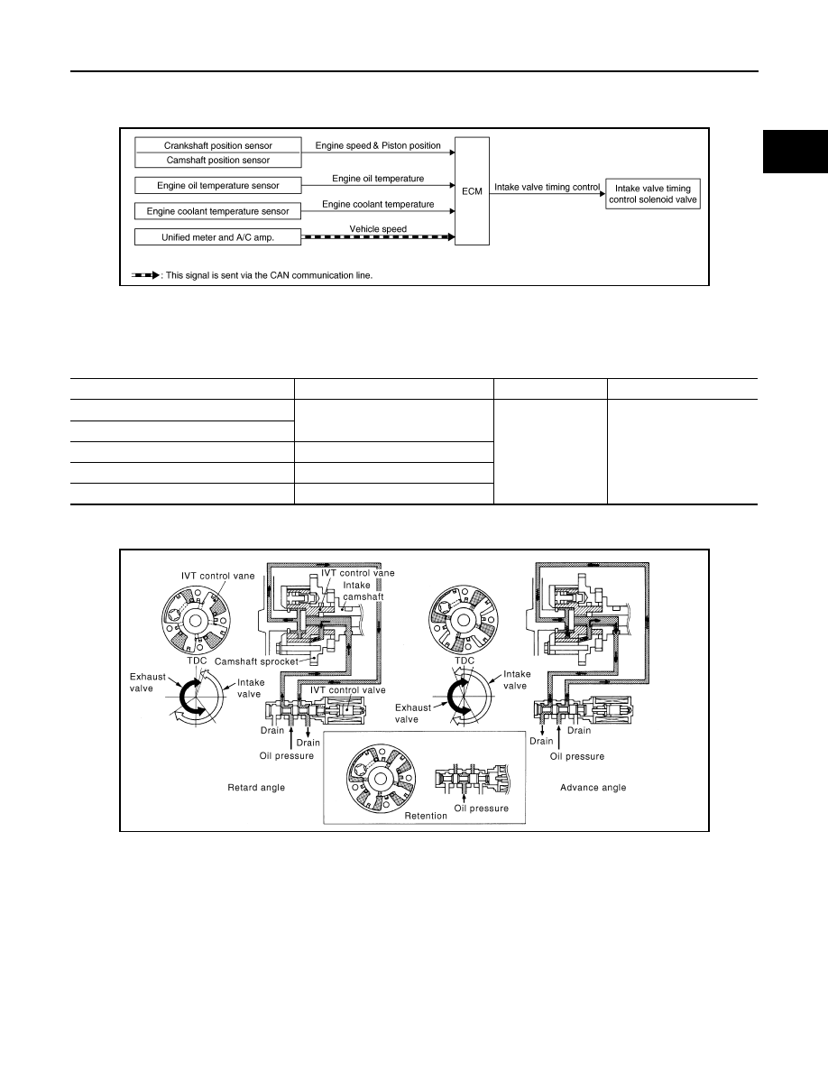
System Diagram
INFOID:0000000005237205
System Description
INFOID:0000000005237206
INPUT/OUTPUT SIGNAL CHART
*: This signal is sent to the ECM via the CAN communication line.
SYSTEM DESCRIPTION
This mechanism hydraulically controls cam phases continuously with the fixed operating angle of the intake
valve.
The ECM receives signals such as crankshaft position, camshaft position, engine speed, and engine coolant
temperature. Then, the ECM sends ON/OFF pulse duty signals to the intake valve timing control solenoid
valve depending on driving status. This makes it possible to control the shut/open timing of the intake valve to
increase engine torque in low/mid speed range and output in high speed range.
JMBIA1532GB
Sensor
Input signal to ECM
ECM function
Actuator
Crankshaft position sensor
Engine speed and piston position
Intake valve timing
control
Intake valve timing control
solenoid valve
Camshaft position sensor
Engine oil temperature sensor
Engine oil temperature
Engine coolant temperature sensor
Engine coolant temperature
Unified meter and A/C amp.
Vehicle speed*
PBIB3276E
EC-686
< SYSTEM DESCRIPTION >
[VK50VE]
INTAKE VALVE TIMING CONTROL
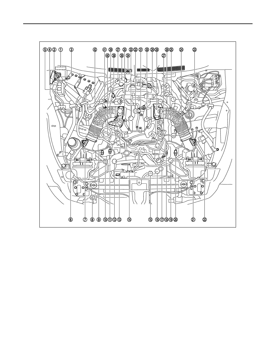
Component Parts Location
INFOID:0000000005589027
1.
IPDM E/R
2.
VVEL control module
3.
Battery current sensor
4.
VVEL actuator motor relay
5.
Cooling fan relay-1
6.
Cooling fan relay-2
7.
Mass air flow sensor (bank 2)
8.
Refrigerant pressure sensor
9.
Exhaust valve timing control position
sensor (bank 2)
10. Exhaust valve timing control sole-
noid valve (bank 2)
11.
Camshaft position sensor (bank 2)
12. Intake valve timing control solenoid
valve (bank 2)
13. Cooling fan motor-1
14. Cooling fan control module-1
15. Cooling fan motor-2
16. Cooling fan control module-2
17. Intake valve timing control solenoid
valve (bank 1)
18. Camshaft position sensor (bank 1)
19. Exhaust valve timing control sole-
noid valve (bank 1)
20. Exhaust valve timing control position
sensor (bank 1)
21. Mass air flow sensor (with intake air
temperature sensor) (bank 1)
22. ICC brake hold relay (ICC models)
23. Brake booster pressure sensor
24. Ignition coil (with power transistor)
and spark plug (bank 1)
25. VVEL actuator motor (bank 1)
26. VVEL control shaft position sensor
(bank 1)
27. Fuel injector (bank 1)
28. Electric throttle control actuator
(bank 1)
29. A/F sensor 1 (bank 1)
30. Knock sensor (bank 1)
JMBIA1535ZZ
INTAKE VALVE TIMING CONTROL
EC-687
< SYSTEM DESCRIPTION >
[VK50VE]
C
D
E
F
G
H
I
J
K
L
M
A
EC
N
P
O
31. EVAP canister purge volume con-
trol solenoid valve
32. Manifold Absolute Pressure Sensor
(This sensor is not for controlling the
engine system, nor for the on board
diagnosis.)
33. Knock sensor (bank 2)
34. Crankshaft position sensor
35. Electric throttle control actuator
(bank2)
36. VVEL actuator motor (bank 2)
37. VVEL control shaft position sensor
(bank 2)
38. A/F sensor 1 (bank 2)
39. Engine coolant temperature sensor
40. Fuel injector (bank 2)
41. EVAP service port
42. Ignition coil (with power transistor)
and spark plug (bank 2)
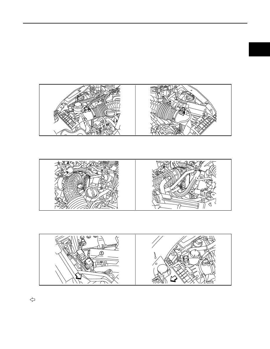
1.
Mass air flow sensor (bank 2)
2.
Mass air flow sensor (with intake air
temperature sensor) (bank 1)
1.
Electric throttle control actuator
(bank 2)
2.
Electric throttle control actuator
(bank 1)
1.
Cooling fan relay-1
2.
Cooling fan relay-2
Vehicle front
JMBIA1536ZZ
JMBIA1537ZZ
JMBIA1538ZZ
EC-688
< SYSTEM DESCRIPTION >
[VK50VE]
INTAKE VALVE TIMING CONTROL
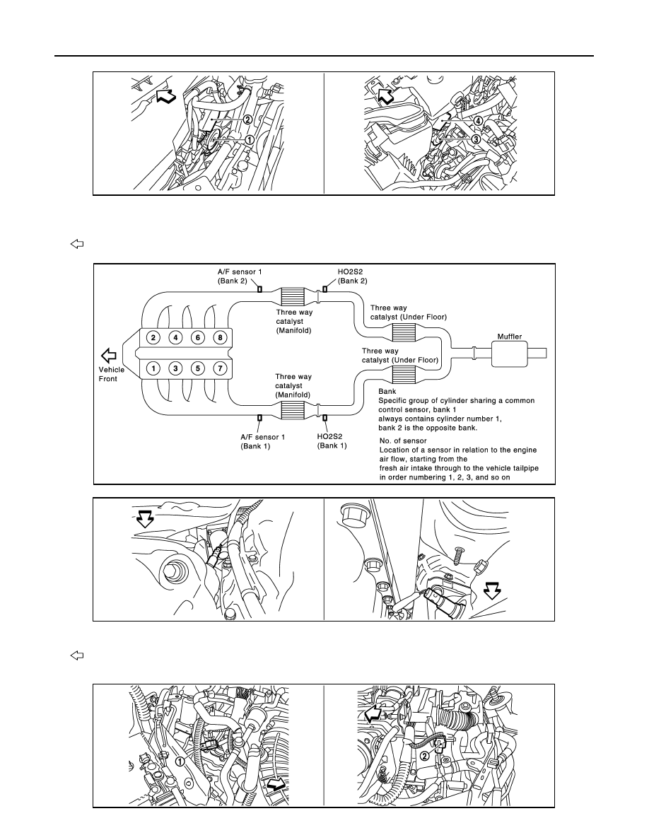
1.
Cooling fan motor-1
2.
Cooling fan control module-1
3.
Cooling fan motor-2
4.
Cooling fan control module-2
Vehicle front
JMBIA1539ZZ
JMBIA1576GB
1.
A/F sensor 1 (bank 1)
2.
A/F sensor 1 (bank 2)
Vehicle front
JMBIA1540ZZ
JMBIA1541ZZ
Нет комментариевНе стесняйтесь поделиться с нами вашим ценным мнением.
Текст