Infiniti FX35, FX50 (S51). Manual — part 1157
AUTOMATIC AIR CONDITIONER SYSTEM
HAC-25
< SYSTEM DESCRIPTION >
[AUTOMATIC AIR CONDITIONER]
C
D
E
F
G
H
J
K
L
M
A
B
HAC
N
O
P
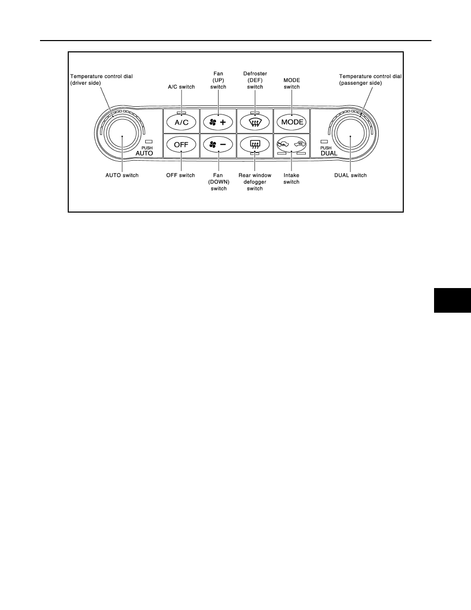
Preset Switch
MODE Switch
The air discharge outlets is controlled with this switch.
Temperature Control Dial (Potentio Temperature Control) (Driver Side)
The set temperature is increased or decreased with this dial.
Temperature Control Dial (Potentio Temperature Control) (Passenger Side)
• The set temperature is increased or decreased with this dial.
• When the temperature control dial is turned, DUAL switch indicator turns ON.
AUTO Switch
• The compressor, intake doors, air mix doors, mode doors and blower speed are automatically controlled so
that the in-vehicle temperature will reach, and be maintained at the set temperature selected by the operator.
• When pressing AUTO switch, air inlet, air outlet, fan speed, and discharge air temperature are automatically
controlled.
Defroster (DEF) Switch
Mode doors are set to the defrost position with this switch. Also, intake doors are set to the outside air position,
and compressor turns ON.
A/C Switch
Compressor is ON or OFF with this switch.
(Pressing the A/C switch when the A/C switch is ON turns OFF the A/C switch and compressor.)
FAN Switches
The blower speed is manually controlled with this switch. Seven speeds are available for manual control (as
shown on the display screen).
OFF Switch
Compressor and blower are OFF, air inlet is set to FRE, and mode position is set to foot position.
Rear Window Defogger Switch
When indicator is ON, rear window is defogged.
Intake Switch
• When intake switch is ON, FRE indicator turns ON, and air inlet is fixed to FRE.
• When intake switch is pressed again, REC indicator turns ON, and air inlet is fixed to REC.
• When intake switch is pressed for approximately 1.5 seconds or longer, FRE and REC indicators blink twice.
Then, automatic control mode is entered. Inlet status is displayed by indicator even during automatic con-
trolled.
• When FRE indicator is turned ON, shifting mode position to D/F or DEF, or when compressor is turned from
ON to OFF, intake switch is automatically turned OFF (fixed to FRE mode). REC mode can be re-entered by
pressing intake switch again, and then compressor is turned ON. (Except D/F or DEF position)
DUAL Switch
JSIIA1070GB
HAC-26
< SYSTEM DESCRIPTION >
[AUTOMATIC AIR CONDITIONER]
AUTOMATIC AIR CONDITIONER SYSTEM
• When the DUAL switch indicator is ON, the driver side and passenger side, temperature can each be set
independently.
• When the DUAL switch indicator is OFF, the driver side outlet and setting temperature is applied to both
sides.
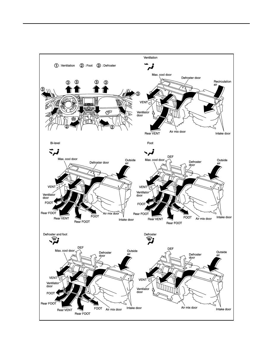
DISCHARGE AIR FLOW
JSIIA1346GB
AUTOMATIC AIR CONDITIONER SYSTEM
HAC-27
< SYSTEM DESCRIPTION >
[AUTOMATIC AIR CONDITIONER]
C
D
E
F
G
H
J
K
L
M
A
B
HAC
N
O
P
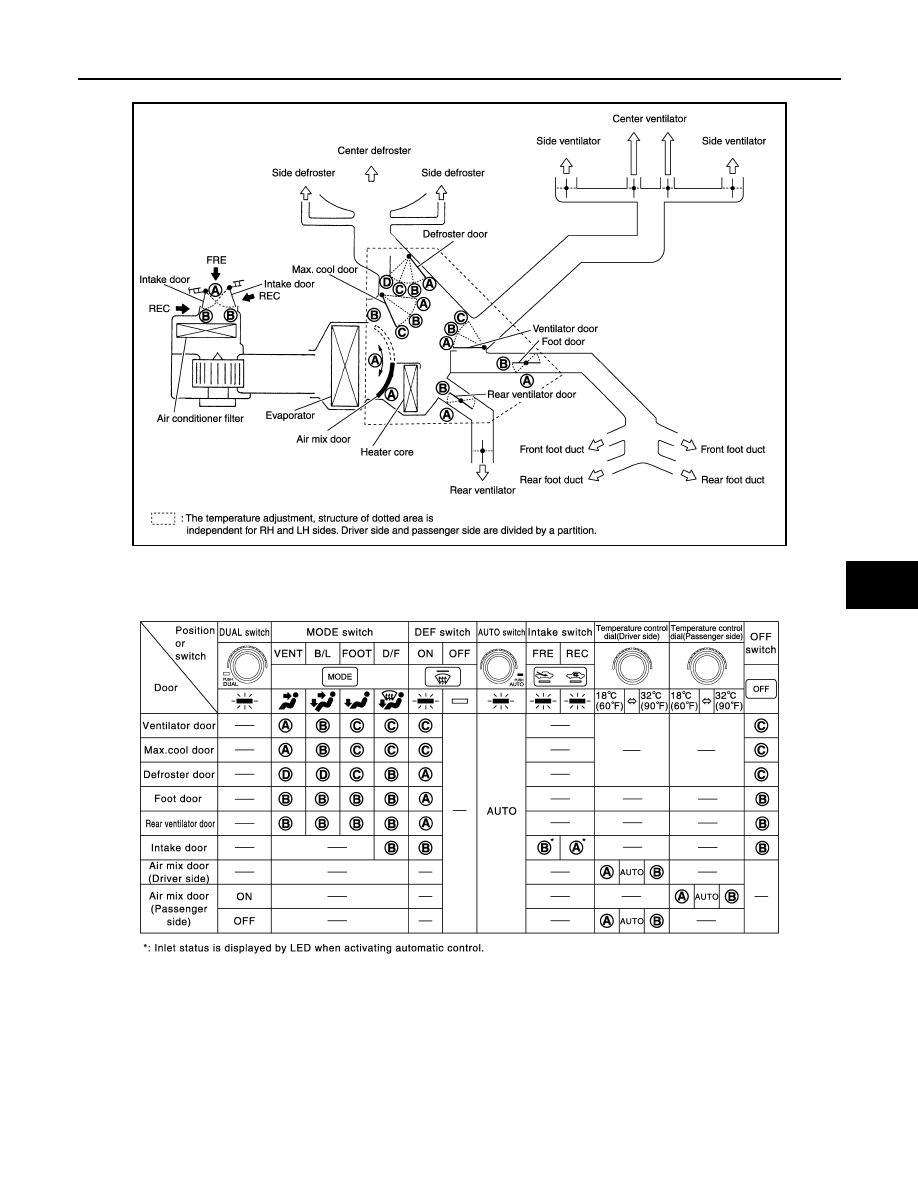
SWITCHES AND THEIR CONTROL FUNCTION
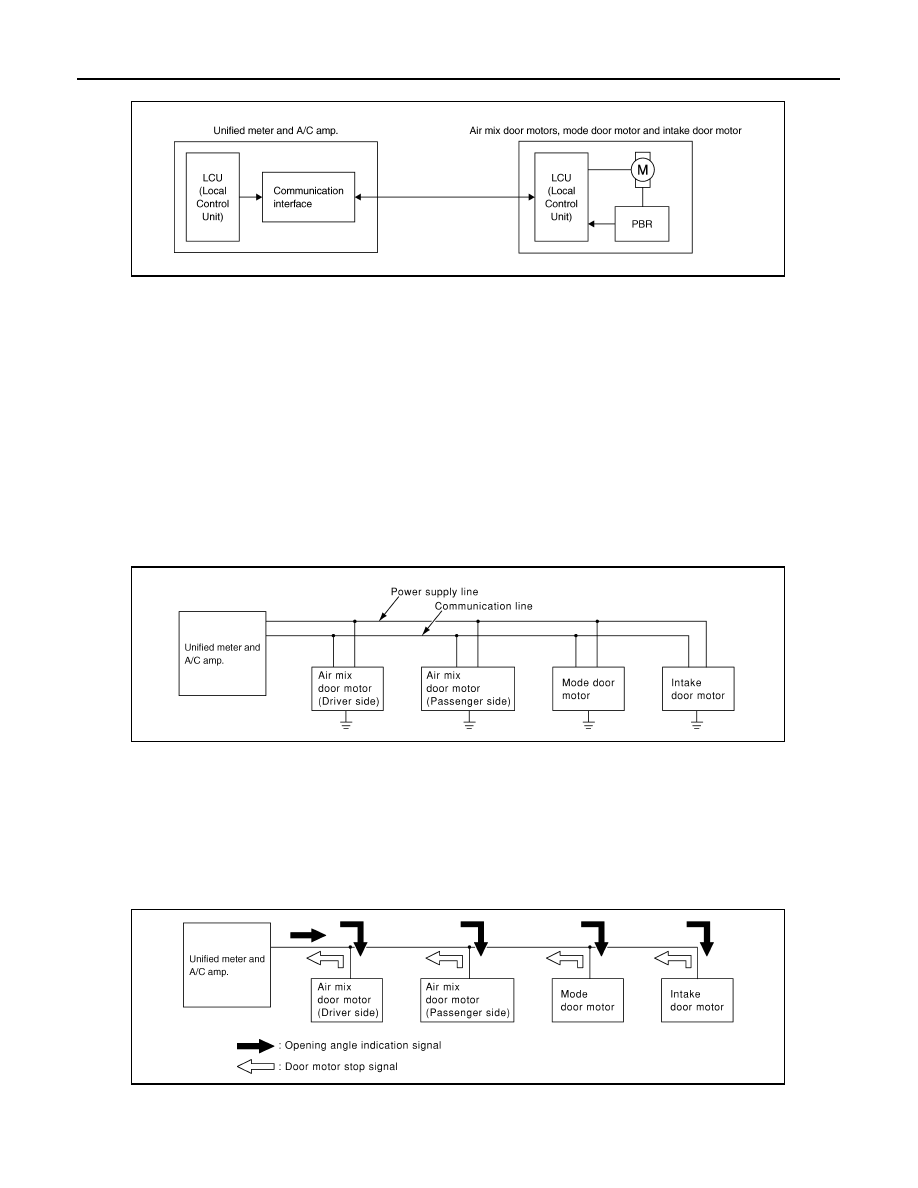
AIR CONDITIONER LAN CONTROL SYSTEM
The LAN (Local Area Network) system consists of unified meter and A/C amp., mode door motor, air mix door
motors and intake door motor.
JSIIA1112GB
JSIIA1004GB
HAC-28
< SYSTEM DESCRIPTION >
[AUTOMATIC AIR CONDITIONER]
AUTOMATIC AIR CONDITIONER SYSTEM
A configuration of these components is as shown in the figure below.
SYSTEM CONSTRUCTION
A small network is constructed between the unified meter and A/C amp., mode door motor, air mix door
motors and intake door motor. The unified meter and A/C amp. and motors are connected by data transmis-
sion lines and motor power supply lines. The LAN network is built through the ground circuits of each door
motor.
Addresses, motor opening angle signals, motor stop signals and error checking messages are all transmitted
through the data transmission lines connecting the unified meter and A/C amp. and each door motor.
The following functions are contained in LCUs built into the mode door motor, the air mix door motors and the
intake door motor.
• Address
• Motor opening angle signals
• Data transmission
• Motor stop and drive decision
• Opening angle sensor (PBR function)
• Comparison
• Decision (Unified meter and A/C amp. indicated value and motor opening angle comparison)
Operation
The unified meter and A/C amp. receives data from each of the sensors. The unified meter and A/C amp.
sends mode door, air mix door and intake door opening angle data to the mode door motor LCU, air mix door
motor LCUs and intake door motor LCU.
The mode door motor, air mix door motors and intake door motor read their respective signals according to the
address signal. Opening angle indication signals received from the unified meter and A/C amp. and each of
the motor position sensors is compared by the LCUs in each door motor with the existing decision and open-
ing angles. Subsequently, HOT/COLD, DEF/VENT and FRE/REC operation is selected. The new selection
data is returned to the unified meter and A/C amp.
Transmission Data and Transmission Order
Unified meter and A/C amp. data is transmitted consecutively to each of the doors motor following the form as
shown in the figure below.
JSIIA0769GB
RJIA1747E
RJIA1748E
Нет комментариевНе стесняйтесь поделиться с нами вашим ценным мнением.
Текст