Infiniti FX35, FX50 (S51). Manual — part 596
DIFFERENTIAL ASSEMBLY
DLN-219
< UNIT DISASSEMBLY AND ASSEMBLY >
[REAR FINAL DRIVE: R200]
C
E
F
G
H
I
J
K
L
M
A
B
DLN
N
O
P
d.
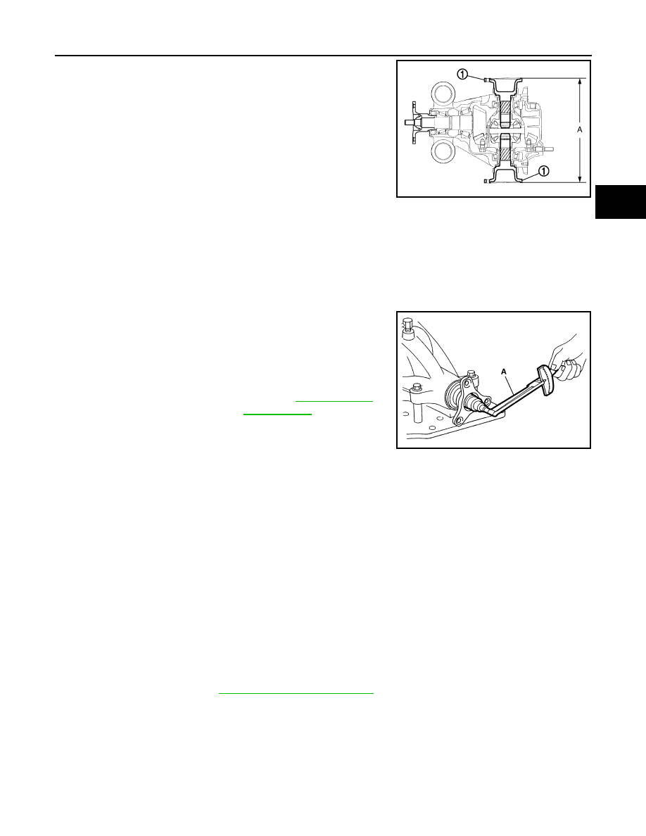
Confirm that the dimension of the side flange (1) installation
measurement (A) in the figure comes into the following.
2WD : Adjustment
INFOID:0000000005249240
TOTAL PRELOAD TORQUE
Before inspection and adjustment, drain gear oil.
1.
Secure final drive assembly onto an attachment [SST: KV38100800 (J-25604-01)].
2.
Remove side flanges.
3.
Rotate drive pinion back and forth 2 to 3 times to check for unusual noise and rotation malfunction.
4.
Rotate drive pinion at least 20 times to check for smooth opera-
tion of the bearing.
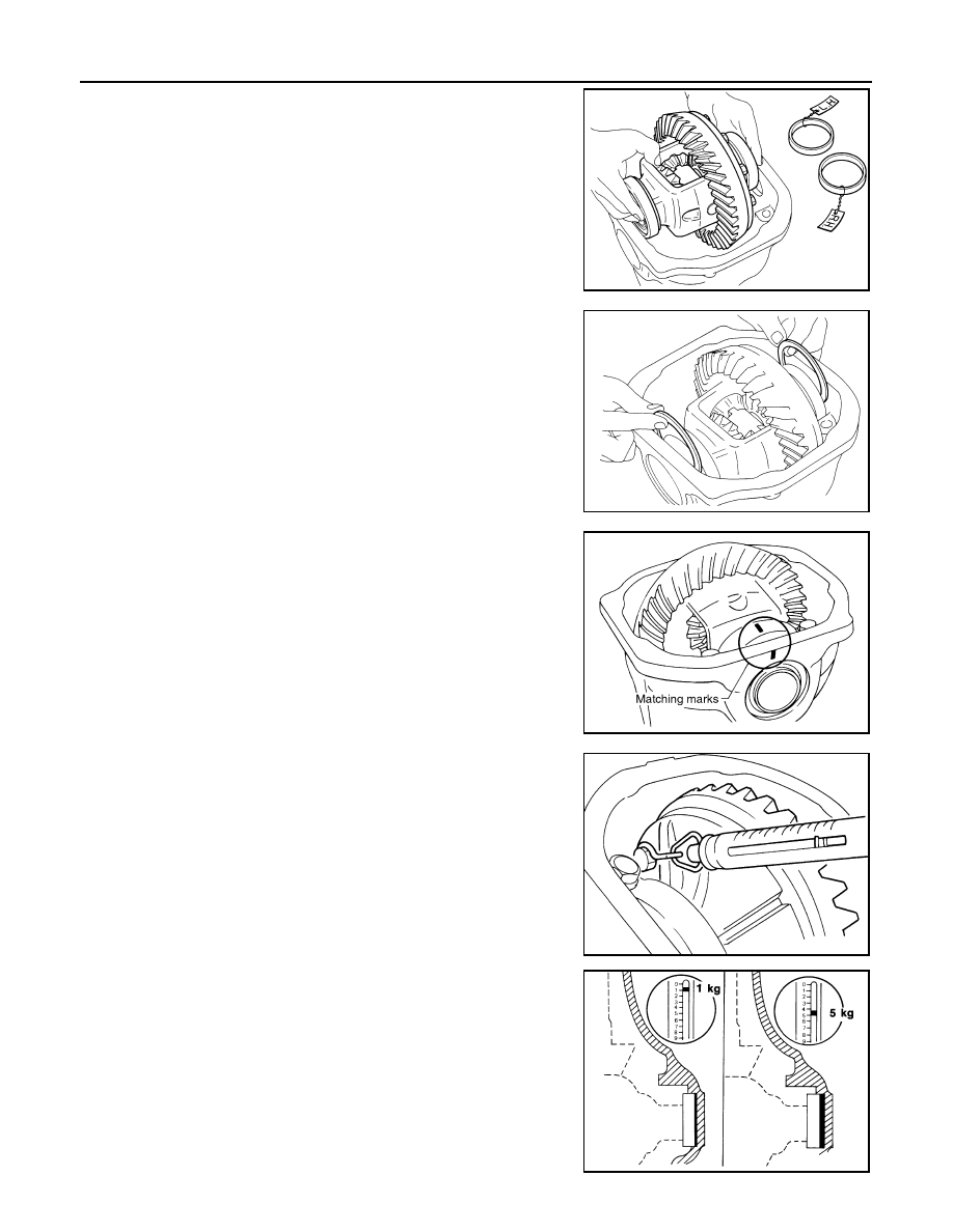
5.
Measure total preload with the preload gauge (A) [SST:
ST3127S000 (J-25765-A)].
NOTE:
Total preload torque = Pinion bearing preload torque + Side
bearing preload torque
• If measured value is out of the specification, disassemble it to check and adjust each part. Adjust the
pinion bearing preload and side bearing preload.
Adjust the pinion bearing preload first, then adjust the side bearing preload.
SIDE BEARING PRELOAD
Before inspection and adjustment, drain gear oil.
1.
Remove rear cover. Refer to
.
Standard
A
: 326 – 328 mm (12.83 – 12.91 in)
JSDIA0106ZZ
Standard
Total preload torque
: Refer to
JSDIA0031ZZ
When the preload torque is large
On pinion bearings:
Replace the collapsible spacer.
On side bearings:
Use thinner side bearing adjusting washers by the same amount to
each side.
When the preload is small
On pinion bearings:
Tighten the drive pinion lock nut.
On side bearings:
Use thicker side bearing adjusting washers by the same amount to
each side.
DLN-220
< UNIT DISASSEMBLY AND ASSEMBLY >
[REAR FINAL DRIVE: R200]
DIFFERENTIAL ASSEMBLY
2.
Make sure all parts are clean. Also, make sure the bearings are
well lubricated with gear oil.
3.
Place the differential case, with side bearings and bearing races
installed, into gear carrier.
4.
Insert left and right original side bearing adjusting washers in
place between side bearings and gear carrier.
5.
Install bearing caps in their correct locations and tighten bearing
cap mounting bolts.
6.
Turn the carrier several times to seat the bearings.
7.
Measure the turning torque of the carrier at the drive gear
mounting bolts with a spring gauge [SST:
—
(J-8129)].
8.
If the turning torque is outside the specification, use a thicker/
thinner side bearing adjusting washer to adjust.
CAUTION:
Select a side bearing adjusting washer for right and left
individually.
SPD527
SPD558
SDIA1795E
Standard
Specification
: 34.2 – 39.2 N (3.5 – 4.0 kg,
7.7 – 8.8 lb) of pulling force
at the drive gear bolt
SPD194A
If the turning torque is less
than the specified range:
Use a thicker thrust wash-
er.
If the turning torque is
greater than the specifica-
tion:
Use a thinner thrust wash-
er.
SPD772
DIFFERENTIAL ASSEMBLY
DLN-221
< UNIT DISASSEMBLY AND ASSEMBLY >
[REAR FINAL DRIVE: R200]
C
E
F
G
H
I
J
K
L
M
A
B
DLN
N
O
P
9.
Record the total amount of washer thickness required for the correct carrier side bearing preload.
DRIVE GEAR RUNOUT
1.
Remove rear cover. Refer to
.
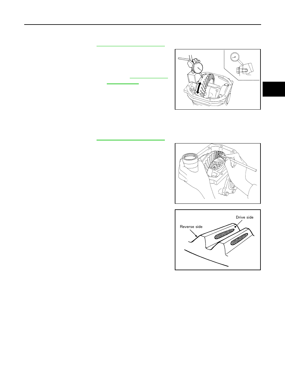
2.
Fit a dial indicator to the drive gear back face.
3.
Rotate the drive gear to measure runout.
• If the runout is outside of the repair limit, check drive gear
assembly condition; foreign material may be caught between
drive gear and differential case, or differential case or drive
gear may be deformed, etc.
CAUTION:
Replace drive gear and drive pinion gear as a set.
TOOTH CONTACT
Before inspection and adjustment, drain gear oil.
1.
Remove rear cover. Refer to
.
2.
Apply red lead to drive gear.
CAUTION:
Apply red lead to both the faces of 3 to 4 gears at 4 loca-
tions evenly spaced on drive gear.
3.
Rotate drive gear back and forth several times, check drive pin-
ion gear to drive gear tooth contact.
CAUTION:
Check tooth contact on drive side and reverse side.
Limit
Drive gear runout
: Refer to
SPD886
SPD357
SDIA0570E
DLN-222
< UNIT DISASSEMBLY AND ASSEMBLY >
[REAR FINAL DRIVE: R200]
DIFFERENTIAL ASSEMBLY
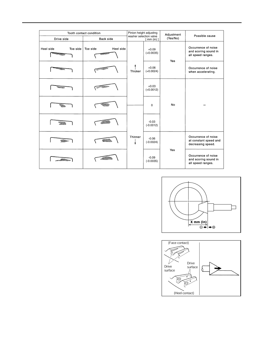
4.
If tooth contact is improperly adjusted, follow the procedure
below to adjust the pinion height [dimension (X)].
• If the tooth contact is near the face (face contact), or near the
heel (heel contact), thicken pinion height adjusting washers to
move drive pinion closer to drive gear.
SDIA0207E
SDIA0517E
PDIA0440E
Нет комментариевНе стесняйтесь поделиться с нами вашим ценным мнением.
Текст