Infiniti EX35. Manual — part 376

CCS
C1A05 BRAKE SW/STOP LAMP SW
CCS-39
< COMPONENT DIAGNOSIS >
[INTELLIGENT CRUISE CONTROL]
C
D
E
F
G
H
I
J
K
L
M
B
N
P
A
>> GO TO 27.
27.
CHECK ICC SYSTEM
1.
Erase DTC and perform ICC system action test. Then perform self-diagnosis of ICC sensor integrated
unit. (For the details on the ICC system action test, refer to
CCS-13, "ACTION TEST : Special Repair
Requirement (Vehicle-To-Vehicle Distance Control Mode)"
).
2.
Check that no abnormal condition is present in the ICC system.
>> INSPECTION END
Component Inspection (ICC BRAKE SWITCH)
INFOID:0000000003130050
1.
CHECK ICC BRAKE SWITCH
Check continuity between ICC brake switch terminals.
Is the inspection result normal?
YES
>> INSPECTION END
NO
>> Replace ICC brake switch.
Component Inspection (STOP LAMP SWITCH)
INFOID:0000000003130051
1.
CHECK STOP LAMP SWITCH
Check continuity between stop lamp switch terminals.
Is the inspection result normal?
YES
>> INSPECTION END
NO
>> Replace stop lamp switch.
terminals
Condition
Continuity
1
2
When brake pedal is depressed
Not existed
When brake pedal is released
Existed
terminals
Condition
Continuity
1
2
When brake pedal is depressed
Existed
When brake pedal is released
Not existed
3
4
When brake pedal is depressed
Existed
When brake pedal is released
Not existed

CCS-40
< COMPONENT DIAGNOSIS >
[INTELLIGENT CRUISE CONTROL]
C1A06 OPERATION SW
C1A06 OPERATION SW
Description
INFOID:0000000003130053
• To activate or deactivate the ICC system and set the vehicle speed and vehicle-to-vehicle distance, use the
ICC steering switch.
• The ICC steering switch signal is inputted to ECM. ECM transmits the data to the ICC sensor integrated unit
with CAN communication.
DTC Logic
INFOID:0000000003130054
DTC DETECTION LOGIC
NOTE:
If DTC “C1A06” is detected along with DTC “U1000” or “U0401”, first diagnose the DTC “U1000” or “U0401”.
• DTC “U1000”: Refer to
.
• DTC “U0401”: Refer to
Diagnosis Procedure
INFOID:0000000003130055
1.
PERFORM SELF-DIAGNOSIS OF ICC SENSOR INTEGRATED UNIT
1.
Perform self-diagnosis of ICC sensor integrated unit.
2.
Check if DTC “U1000: CAN COMM CIRCUIT” (DTC 100) or “U0401: ECM CAN CIR 1” (DTC 120) other
than “C1A06: OPERATION SW CIRC” (DTC 6) is detected.
Is any DTC detected?
YES
>> GO TO 2.
NO
>> GO TO 3.
2.
DIAGNOSIS FOR DETECTED DTC
Perform diagnosis on the detected DTC and repair or replace the applicable item. Refer to
.
>> GO TO 12.
3.
CHECK CONNECTOR OF ECM
1.
Turn ignition switch OFF.
2.
Disconnect ECM connector, and connect it securely again.
3.
Erase DTC.
4.
Operate the ICC steering switch.
5.
Perform self-diagnosis of ICC sensor integrated unit.
6.
Check if DTC “C1A06: OPERATION SW CIRC” (DTC 6) is detected.
Is any DTC detected?
YES
>> GO TO 5.
NO
>> GO TO 4.
4.
CHECK ECM CONNECTOR
1.
Check ECM connector housing for disconnected, loose, bent, and collapsed terminals.
2.
Repair or replace the applicable item if any abnormal condition is found.
>> GO TO 12.
5.
CHECK ICC STEERING SWITCH
DTC No.
(On board
display)
Trouble diagnosis name
DTC detecting condition
Possible cause
C1A06
(6)
OPERATION SW CIRC
If any abnormal condition is present in the input
signal from the ICC steering switch.
• ICC steering switch circuit
• ICC steering switch
• ECM

CCS
C1A06 OPERATION SW
CCS-41
< COMPONENT DIAGNOSIS >
[INTELLIGENT CRUISE CONTROL]
C
D
E
F
G
H
I
J
K
L
M
B
N
P
A
1.
Turn ignition switch OFF.
2.
Disconnect ICC steering switch connector.
3.
Check ICC steering switch. Refer to
CCS-42, "Component Inspection"
Is the inspection result normal?
YES
>> GO TO 7.
NO
>> GO TO 6.
6.
REPLACE ICC STEERING SWITCH
Replace ICC steering switch.
>> GO TO 12.
7.
CHECK ICC STEERING SWITCH SIGNAL CIRCUIT
1.
Disconnect spiral cable connector and ECM connector.
2.
Check continuity between spiral cable harness connector and ECM harness connector.
3.
Check continuity between spiral cable harness connector and ground.
Is the inspection result normal?
YES
>> GO TO 9.
NO
>> GO TO 8.
8.
REPAIR OR REPLACE HARNESS BETWEEN SPIRAL CABLE AND ECM
Repair or replace harness between spiral cable and ECM.
>> GO TO 12.
9.
CHECK COMBINATION SWITCH (SPIRAL CABLE)
Check continuity between spiral cable terminals.
Is the inspection result normal?
YES
>> GO TO 11.
NO
>> GO TO 10.
10.
REPLACE SPIRAL CABLE
Replace spiral cable.
>> GO TO 12.
11.
PERFORM SELF-DIAGNOSIS OF ECM
1.
Perform self-diagnosis of ECM.
Spiral cable
ECM
Continuity
Connector
Terminal Connector
Terminal
M36
25
M107
101
Existed
32
108
Spiral cable
Ground
Continuity
Connector
Terminal
M36
25
Not existed
32
M36
M303
Continuity
Terminal Terminal
25
13
Existed
32
16
CCS-42
< COMPONENT DIAGNOSIS >
[INTELLIGENT CRUISE CONTROL]
C1A06 OPERATION SW
2.
Repair or replace applicable item. Refer to
>> GO TO 12.
12.
CHECK ICC SYSTEM
1.
Erase DTC and perform ICC system action test. Then perform self-diagnosis of ICC sensor integrated
unit. (For the details on the ICC system action test, refer to
CCS-13, "ACTION TEST : Special Repair
Requirement (Vehicle-To-Vehicle Distance Control Mode)"
).
2.
Check that no abnormal condition is present in the ICC system.
>> INSPECTION END
Component Inspection
INFOID:0000000003130056
1.
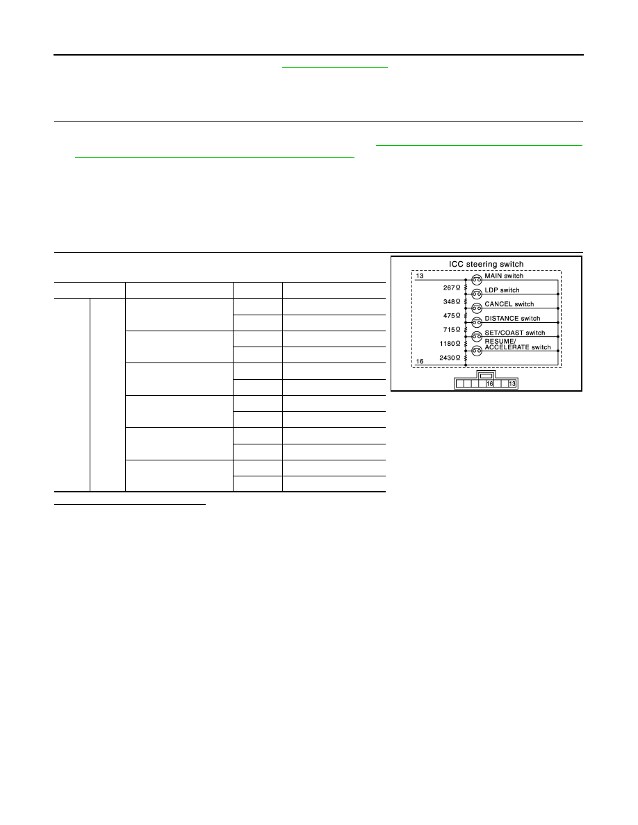
CHECK ICC STEERING SWITCH
Check resistance between terminals by pressing each switch.
Is the inspection result normal?
YES
>> INSPECTION END
NO
>> Replace ICC steering switch.
Terminal
Switch
Condition
Resistance [
Ω
]
13
16
MAIN
Pressed
Approx. 0
Released
Approx. 5415
LDP
Pressed
Approx. 267
Released
Approx. 5415
CANCEL
Pressed
Approx. 615
Released
Approx. 5415
DISTANCE
Pressed
Approx. 1090
Released
Approx. 5415
SET/COAST
Pressed
Approx. 1805
Released
Approx. 5415
RESUME/ACCELERATE
Pressed
Approx. 2985
Released
Approx. 5415
JPOIA0109ZZ
Нет комментариевНе стесняйтесь поделиться с нами вашим ценным мнением.
Текст