Infiniti EX35. Manual — part 1405
TM-8
< FUNCTION DIAGNOSIS >
[5AT: RE5R05A]
A/T CONTROL SYSTEM
FUNCTION DIAGNOSIS
A/T CONTROL SYSTEM
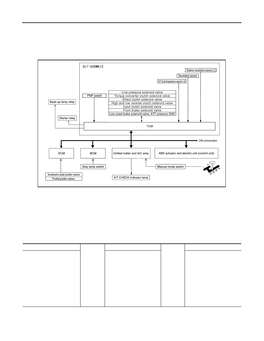
System Diagram
INFOID:0000000003130457
System Description
INFOID:0000000003130458
The A/T senses vehicle operating conditions through various sensors or signals. It always controls the opti-
mum shift position and reduces shifting and lock-up shocks.
TCM FUNCTION
The function of the TCM is to:
• Receive input signals transmitted from various switches and sensors.
• Determine required line pressure, shifting point, lock-up operation, engine brake operation, etc.
• Transmit required output signals to the respective solenoids.
Input/Output Signal of TCM
JSDIA0122GB
SENSORS (or SIGNALS)
⇒
TCM
⇒
ACTUATORS
PNP switch
Accelerator pedal position signal
Closed throttle position signal
Wide open throttle position signal
Engine speed signal
A/T fluid temperature sensor
Revolution sensor
Vehicle speed signal
Manual mode switch signal
Stop lamp switch signal
Turbine revolution sensor
ATF pressure switch
Shift control
Line pressure control
Lock-up control
Engine brake control
Timing control
Fail-safe control
Self-diagnosis
CONSULT-III communication
line
Duet-EA control
CAN system
Input clutch solenoid valve
Direct clutch solenoid valve
Front brake solenoid valve
High and low reverse clutch sole-
noid valve
Low coast brake solenoid valve
Torque converter clutch solenoid
valve
Line pressure solenoid valve
A/T CHECK indicator lamp
Back-up lamp relay
Starter relay
A/T CONTROL SYSTEM
TM-9
< FUNCTION DIAGNOSIS >
[5AT: RE5R05A]
C
E
F
G
H
I
J
K
L
M
A
B
TM
N
O
P
*1: Spare for vehicle speed sensor·A/T (revolution sensor)
*2: Spare for accelerator pedal position signal
*3: If these input and output signals are different, the TCM triggers the fail-safe function.
*4: Used as a condition for starting self-diagnostics; if self-diagnostics are not started, it is judged that there is some kind of error.
*5: Input by CAN communications.
*6: Output by CAN communications.
CAN COMMUNICATION
CAN (Controller Area Network) is a serial communication line for real-time application. It is an on-vehicle mul-
tiplex communication line with high data communication speed and excellent error detection ability. Many elec-
tronic control units are equipped onto a vehicle, and each control unit shares information and links with other
control units during operation (not independently). In CAN communication, control units are connected with 2
communication lines (CAN-H line, CAN-L line) allowing a high rate of information transmission with less wiring.
Each control unit transmits/receives data but selectively reads required data only. Refer to
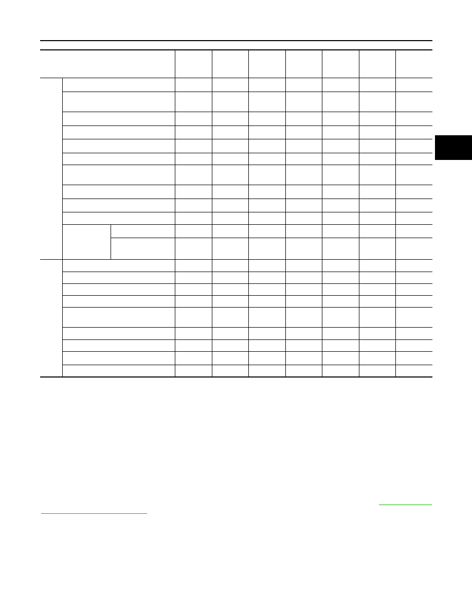
LINE PRESSURE CONTROL
• When an input torque signal equivalent to the engine drive force is transmitted from the ECM to the TCM,
the TCM controls the line pressure solenoid valve.
Control item
Line
pressure
control
Vehicle
speed
control
Shift
control
Lock-up
control
Engine
brake
control
Fail-safe
function
*3
Self-diag-
nostics
function
Input
Accelerator pedal position signal
*5
X
X
X
X
X
X
X
Vehicle speed sensor A/T
(revolution sensor)
X
X
X
X
X
X
X
Vehicle speed sensor MTR
*1, *5
X
Closed throttle position signal
*5
X
*2
X
X
X
X
*4
Wide open throttle position signal
*5
X
X
*4
Turbine revolution sensor 1
X
X
X
X
X
Turbine revolution sensor 2
(for 4th speed only)
X
X
X
X
X
Engine speed signals
*5
X
X
X
X
X
X
X
Stop lamp switch signal
*5
X
X
X
X
*4
A/T fluid temperature sensors 1, 2
X
X
X
X
X
X
ASCD or ICC
sensor inte-
grated unit
Operation signal
*5
X
X
X
Overdrive cancel
signal
*5
X
Out-
put
Direct clutch solenoid
X
X
X
X
Input clutch solenoid
X
X
X
X
High and low reverse clutch solenoid
X
X
X
X
Front brake solenoid
X
X
X
X
Low coast brake solenoid
(ATF pressure switch 2)
X
X
X
X
X
Line pressure solenoid
X
X
X
X
X
X
X
TCC solenoid
X
X
X
A/T CHECK indicator lamp
*6
X
*4
Starter relay
X
X
TM-10
< FUNCTION DIAGNOSIS >
[5AT: RE5R05A]
A/T CONTROL SYSTEM
• This line pressure solenoid controls the pressure regulator valve as the signal pressure and adjusts the pres-
sure of the operating oil discharged from the oil pump to the line pressure most appropriate to the driving
state.
Line Pressure Control is Based On The TCM Line Pressure Characteristic Pattern
• The TCM has stored in memory a number of patterns for the optimum line pressure characteristic for the
driving state.
• In order to obtain the most appropriate line pressure characteristic to meet the current driving state, the TCM
controls the line pressure solenoid current value and thus controls the line pressure.
Normal Control
• Each clutch is adjusted to the necessary pressure to match the
engine drive force.
Back-up Control (Engine Brake)
• When the select operation is performed during driving and the A/T
is shifted down, the line pressure is set according to the vehicle
speed.
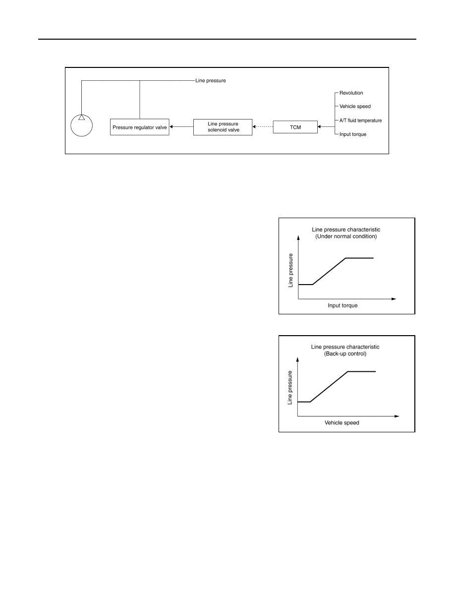
During Shift Change
PCIA0007E
PCIA0008E
PCIA0009E
A/T CONTROL SYSTEM
TM-11
< FUNCTION DIAGNOSIS >
[5AT: RE5R05A]
C
E
F
G
H
I
J
K
L
M
A
B
TM
N
O
P
• The necessary and adequate line pressure for shift change is set.
For this reason, line pressure pattern setting corresponds to input
torque and gearshift selection. Also, line pressure characteristic
corresponds to engine speed, during engine brake operation.
At Low Fluid Temperature
• When the A/T fluid temperature drops below the prescribed tem-
perature, in order to speed up the action of each friction element,
the line pressure is set higher than the normal line pressure char-
acteristic.
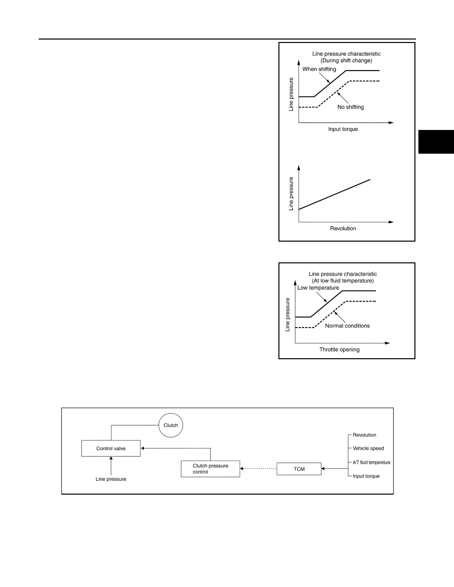
SHIFT CONTROL
The clutch pressure control solenoid is controlled by the signals from the switches and sensors. Thus, the
clutch pressure is adjusted to be appropriate to the engine load state and vehicle driving state. It becomes
possible to finely control the clutch hydraulic pressure with high precision and a smoother shift change charac-
teristic is attained.
Shift Change
The clutch is controlled with the optimum timing and oil pressure by the engine speed, engine torque informa-
tion, etc.
PCIA0010E
PCIA0011E
PCIA0012E
Нет комментариевНе стесняйтесь поделиться с нами вашим ценным мнением.
Текст