Infiniti EX35. Manual — part 1411
TM-32
< FUNCTION DIAGNOSIS >
[5AT: RE5R05A]
SHIFT MECHANISM
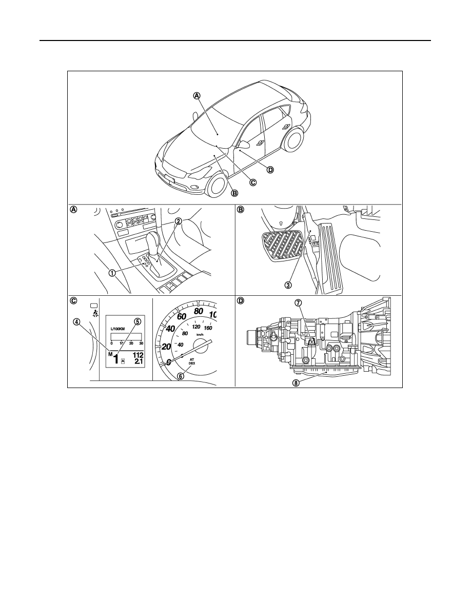
Component Parts Location
INFOID:0000000003508908
*: Control valve with TCM is included in A/T assembly.
NOTE:
• The following components are included in control device assembly (2).
- Manual mode select switch
- Manual mode position select switch
- Shift position switch
• The following components are included in control valve with TCM (8).
- TCM
- Turbine revolution sensor 1, 2
- Revolution sensor
- A/T fluid temperature sensor 1, 2
- PNP switch
- Line pressure solenoid valve
- Torque converter clutch solenoid valve
- Direct clutch solenoid valve
1.
Selector lever position indicator
2.
Control device assembly
3.
Accelerator pedal position sensor
4.
Manual mode indicator
5.
Shift position indicator
6.
A/T CHECK indicator lamp
7.
A/T assembly harness connector
8.
Control valve with TCM*
A.
Center console
B.
Accelerator pedal
C.
Combination meter
D.
A/T assembly
JPDIA0670ZZ

SHIFT MECHANISM
TM-33
< FUNCTION DIAGNOSIS >
[5AT: RE5R05A]
C
E
F
G
H
I
J
K
L
M
A
B
TM
N
O
P
- High and low reverse clutch solenoid valve
- Input clutch solenoid valve
- Front brake solenoid valve
- Low coast brake solenoid valve
- ATF pressure switch 2
Component Description
INFOID:0000000003130465
Name of the Part (Abbreviation)
Function
Front brake (FR/B)
Fastens the front sun gear.
Input clutch (I/C)
Connects the input shaft, the front internal gear and the mid internal gear.
Direct clutch (D/C)
Connects the rear carrier and the rear sun gear.
High and low reverse clutch (HLR/C)
Connects the mid sun gear and the rear sun gear.
Reverse brake (R/B)
Fastens the rear carrier.
Forward brake (Fwd/B)
Fastens the mid sun gear.
Low coast brake (LC/B)
Fastens the mid sun gear.
1st one-way clutch (1st OWC)
Allows the rear sun gear to turn freely forward relative to the mid sun gear but fastens it for
reverse rotation.
Forward one-way clutch (Fwd OWC)
Allows the mid sun gear to turn freely in the forward direction but fastens it for reverse ro-
tation.
3rd one-way clutch (3rd OWC)
Allows the front sun gear to turn freely in the forward direction but fastens it for reverse ro-
tation.
Torque converter
Amplifies driving force the engine, and transmits it to transmission input shaft.
Oil pump
Driven by the engine, oil pump supplies oil to torque converter, control valve assembly, and
each lubricating system.
TM-34
< FUNCTION DIAGNOSIS >
[5AT: RE5R05A]
SHIFT LOCK SYSTEM
SHIFT LOCK SYSTEM
System Description
INFOID:0000000003130466
The selector lever cannot be shifted from the “P” position unless the brake pedal is depressed while the igni-
tion switch is ON.
The shift lock is unlocked by the shift lock unit that is activated when the ignition switch is ON and the stop
lamp switch is turned ON (brake pedal is depressed).
Therefore, the shift lock unit receives no ON signal and the shift lock remains locked if the above conditions
are not fulfilled. (However, a shift operation is allowed if the shift lock release button is pressed.)
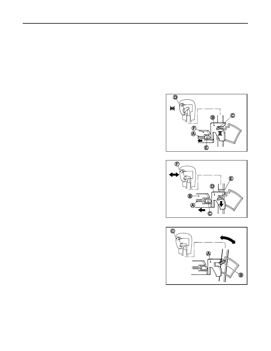
SHIFT LOCK OPERATION AT “P” POSITION
When Brake Pedal Is Not Depressed (No Shift Operation Allowed)
The shift lock solenoid (A) inside the shift lock unit is not energized if
the brake pedal is not depressed while the ignition switch is ON.
The lock plate (B) lowers according to the downward movement of
the position pin (C) when the selector button (D) is pressed, and
presses only slider B (E) into the shift lock unit. Slider A (F) located
below the lock plate prevents the downward movement of the lock
plate with the spring force. The selector lever cannot be shifted from
the “P” position for this reason.
However, slider A is forcibly pressed into the shift lock unit, allowing
the selector lever to shift if the shift lock release button is pressed.
When Brake Pedal Is Depressed (Shift Operation Allowed)
The shift lock solenoid (A) inside the shift lock unit is energized and
the relative positions of sliders A (B) and B (C) are maintained when
the brake pedal is depressed while the ignition switch is ON.
The lock plate (D) lowers according to the downward movement of
the position pin (E), thrusting away sliders A and B, when the selec-
tor button (F) is pressed.
The position pin lowers to the position that allows shift operation for
this reason. As a result, the selector lever can be shifted out of the P
position.
OPERATION AT OTHER THAN “P” POSITION
The shift lock function will not operate at any position other than “P”
because the lock plate (A) is only set for the “P” position. Accord-
ingly, the selector lever can be shifted to any position regardless of
the brake operation.
The position pin (B) enters the “P” position thrusting away the lock
plate when the selector lever is shifted to the “P” position. Then, the
shift mechanism is locked when the selector button (C) is released.
“P” POSITION RETAINING MECHANISM (IGNITION SWITCH LOCK)
When ignition switch is not in the ON position, power is not applied to the shift lock solenoid in the shift lock
unit. This causes shift lock state, and then “P” position is retained.
When an actuating system in the shift lock unit has a malfunction, selector lever is unable to operate from the
“P” position even when pressing the brake pedal with the ignition switch ON. However, when pressing the shift
lock release button, slider A is forcibly pressed into the shift lock unit. This allows shift lock to be released and
selector lever enables the select operation from the “P” position.
CAUTION:
Do not use the shift lock release button except when the select lever is inoperative even when press-
ing the brake pedal with the ignition switch ON.
JSDIA0119ZZ
JSDIA0120ZZ
JSDIA0121ZZ
SHIFT LOCK SYSTEM
TM-35
< FUNCTION DIAGNOSIS >
[5AT: RE5R05A]
C
E
F
G
H
I
J
K
L
M
A
B
TM
N
O
P
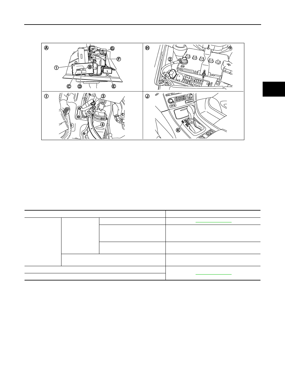
Component Parts Location
INFOID:0000000003130467
*: Shift lock release button becomes operative by removing shift lock cover.
Component Description
INFOID:0000000003130468
1.
Shift lock unit
2.
Shift lock relay
3.
Stop lamp switch
4.
Brake pedal
A.
Control device assembly
B.
Slider B
C.
Shift lock solenoid
D.
Slider A
E.
Control device harness connector
F.
Lock plate
G.
Position pin
H.
Fuse, fusible link and relay box
I.
Brake pedal, upper
J.
A/T console finisher
K.
Shift lock cover *
JPDIA0633ZZ
Component
Function
Control device as-
sembly
Shift lock unit
Shift lock solenoid
Lock plate
The lock plate restricts the position pin stroke by se-
lector button operation according to the shift lock unit
status.
Shift lock release button
Pressing the shift lock release button cancels the
shift lock forcibly.
Position pin
The position pin, linking with the selector button, re-
stricts the selector lever movement.
Shift lock relay
Stop lamp switch
Нет комментариевНе стесняйтесь поделиться с нами вашим ценным мнением.
Текст