Infiniti EX35. Manual — part 987
LAN
LAN-7
C
D
E
F
G
H
I
J
K
L
B
A
O
P
N
IPDM-E BRANCH LINE CIRCUIT . . . . .
Diagnosis Procedure . . . . . . . . . . . .
CAN COMMUNICATION CIRCUIT . . . . .
LAN-8
< PRECAUTION >
[CAN FUNDAMENTAL]
PRECAUTIONS
PRECAUTION
PRECAUTIONS
Precautions for Trouble Diagnosis
INFOID:0000000003516090
CAUTION:
• Never apply 7.0 V or more to the measurement terminal.
• Use a tester with open terminal voltage of 7.0 V or less.
• Turn the ignition switch OFF and disconnect the battery cable from the negative terminal when
checking the harness.
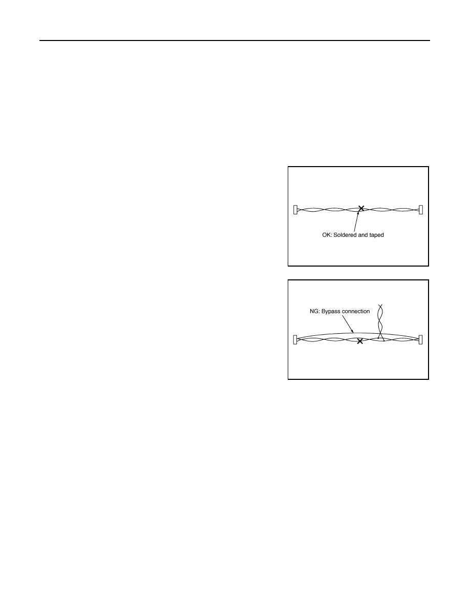
Precautions for Harness Repair
INFOID:0000000003516091
• Solder the repaired area and wrap tape around the soldered area.
NOTE:
A fray of twisted lines must be within 110 mm (4.33 in).
• Bypass connection is never allowed at the repaired area.
NOTE:
Bypass connection may cause CAN communication error. The
spliced wire becomes separated and the characteristics of twisted
line are lost.
• Replace the applicable harness as an assembly if error is detected on the shield lines of CAN communica-
tion line.
SKIB8766E
SKIB8767E
LAN
CAN COMMUNICATION SYSTEM
LAN-9
< FUNCTION DIAGNOSIS >
[CAN FUNDAMENTAL]
C
D
E
F
G
H
I
J
K
L
B
A
O
P
N
FUNCTION DIAGNOSIS
CAN COMMUNICATION SYSTEM
System Description
INFOID:0000000003516092
• CAN communication is a multiplex communication system. This enables the system to transmit and receive
large quantities of data at high speed by connecting control units with two communication lines (CAN-H and
CAN-L).
• Control units on the CAN network transmit signals using the CAN communication control circuit. They
receive only necessary signals from other control units to operate various functions.
• CAN communication lines adopt twisted-pair line style (two lines twisted) for noise immunity.
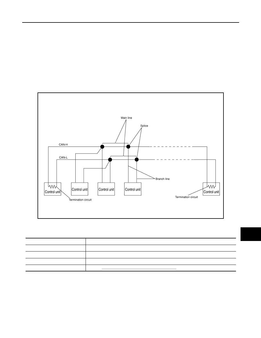
System Diagram
INFOID:0000000003516093
Each control unit passes an electric current to the termination circuits when transmitting CAN communication
signal. The termination circuits produce an electrical potential difference between CAN-H and CAN-L. CAN
communication system transmits and receives CAN communication signals by the potential difference.
SKIB8887E
Component
Description
Main line
CAN communication line between splices
Branch line
CAN communication line between splice and a control unit
Splice
A point connecting a branch line with a main line
Termination circuit
LAN-10, "CAN Communication Control Circuit"
.

LAN-10
< FUNCTION DIAGNOSIS >
[CAN FUNDAMENTAL]
CAN COMMUNICATION SYSTEM
CAN Communication Control Circuit
INFOID:0000000003516094
*: These are the only control units wired with both ends of CAN communication system.
SKIB8713E
Component
System description
CAN controller
It controls CAN communication signal transmission and reception, error detection, etc.
Transceiver IC
It converts digital signal into CAN communication signal, and CAN communication signal into digital
signal.
Noise filter
It eliminates noise of CAN communication signal.
Termination circuit
*
(Resistance of approx. 120
Ω
)
It produces potential difference.
Нет комментариевНе стесняйтесь поделиться с нами вашим ценным мнением.
Текст