Infiniti EX35. Manual — part 931

HAC-120
< ECU DIAGNOSIS >
[AUTOMATIC AIR CONDITIONER]
ECM
101
Ground
SB
ICC steering switch
(models with ICC sys-
tem)
Input
[Ignition switch: ON]
• ICC steering switch: OFF
4.3V
[Ignition switch: ON]
• MAIN switch: Pressed
0V
[Ignition switch: ON]
• CANCEL switch: Pressed
1.3V
[Ignition switch: ON]
• RESUME/ACCELERATE
switch: Pressed
3.7V
[Ignition switch: ON]
• SET/COAST switch: Pressed
3V
[Ignition switch: ON]
• DISTANCE switch: Pressed
2.2V
101
Ground
SB
ASCD steering switch
(models with ASCD sys-
tem)
Input
[Ignition switch: ON]
• ASCD steering switch: OFF
4V
[Ignition switch: ON]
• MAIN switch: Pressed
0V
[Ignition switch: ON]
• CANCEL switch: Pressed
1V
[Ignition switch: ON]
• RESUME/ACCELERATE
switch: Pressed
3V
[Ignition switch: ON]
• SET/COAST switch: Pressed
2V
102
Ground
LG
EVAP control system
pressure sensor
Input
[Ignition switch: ON]
1.8 - 4.8V
103
Ground
G
Sensor power supply
(Accelerator pedal posi-
tion sensor 2)
—
[Ignition switch: ON]
5V
104
Ground
GR
Sensor ground
(Accelerator pedal posi-
tion sensor 2)
—
[Ignition switch: ON]
• Warm-up condition
• Idle speed
0V
105
Ground
L
Refrigerant pressure
sensor
Input
[Engine is running]
• Warm-up condition
• Both A/C switch and blower fan
motor switch: ON (Compressor
operates)
1.0 - 4.0V
106
Ground
W
Fuel tank temperature
sensor
Input
[Engine is running]
0 - 4.8V
Output voltage varies with fuel
tank temperature.
107
Ground
BR
Sensor power supply
(EVAP control system
pressure sensor)
—
[Ignition switch: ON]
5V
108
Ground
Y
Sensor ground
(ASCD/ICC steering
switch)
—
[Engine is running]
• Warm-up condition
• Idle speed
0V
109
Ground
G (A/
T)
BR
(M/T)
PNP switch
Input
[Ignition switch: ON]
• Selector lever: P or N (A/T), Neu-
tral (M/T)
BATTERY VOLTAGE
(11 - 14V)
[Ignition switch: ON]
• Selector lever: Except above
0V
Terminal No.
Wire
color
Description
Condition
Value
(Approx.)
+
-–
Signal name
Input/
Output
ECM
HAC-121
< ECU DIAGNOSIS >
[AUTOMATIC AIR CONDITIONER]
C
D
E
F
G
H
J
K
L
M
A
B
HAC
N
O
P
: Average voltage for pulse signal (Actual pulse signal can be confirmed by oscilloscope.)
*1: This may vary depending on internal resistance of the tester.
**2: Before measuring the terminal voltage, confirm that the battery is fully charged. Refer to
.
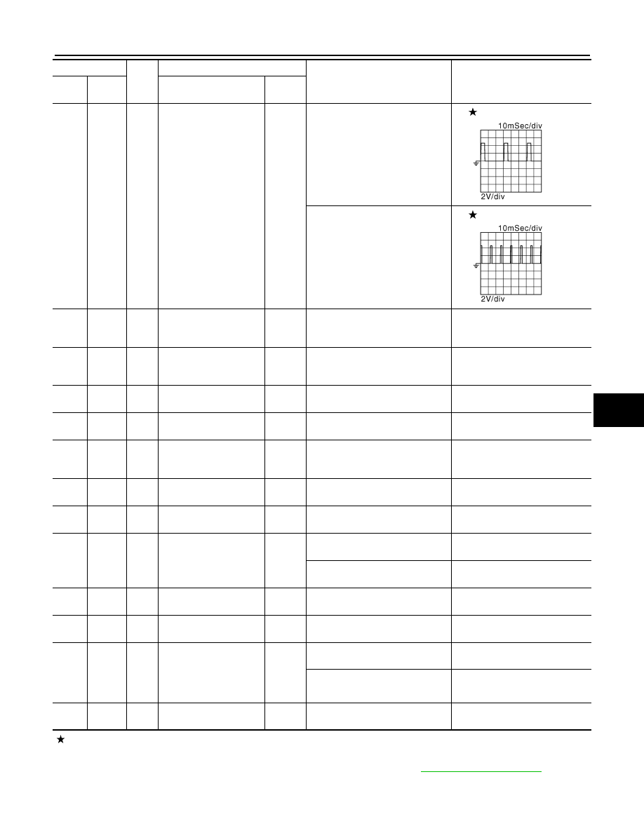
110
Ground
R
Engine speed output sig-
nal
Output
[Engine is running]
• Warm-up condition
• Idle speed
NOTE:
The pulse cycle changes de-
pending on rpm at idle
1V
[Engine is running]
• Engine speed is 2,000 rpm
1V
111
Ground
O
Sensor power supply
(Refrigerant pressure
sensor)
—
[Ignition switch: ON]
5V
112
Ground
V
Sensor ground
(EVAP control system
pressure sensor)
—
[Engine is running]
• Warm-up condition
• Idle speed
0V
113
Ground
P
CAN communication line
Input/
Output
—
—
114
Ground
L
CAN communication line
Input/
Output
—
—
116
Ground
W
Sensor ground
(Refrigerant pressure
sensor)
—
[Engine is running]
• Warm-up condition
• Idle speed
0V
117
Ground
V
Data link connector
Input/
Output
[Ignition switch: ON]
• GST: Disconnected
5V - BATTERY VOLTAGE (11 -
14V)
121
Ground
LG
EVAP canister vent con-
trol valve
Output
[Ignition switch: ON]
BATTERY VOLTAGE
(11 - 14V)
122
Ground
P
Stop lamp switch
Input
[Ignition switch: OFF]
• Brake pedal: Fully released
0V
[Ignition switch: OFF]
• Brake pedal: Slightly depressed
BATTERY VOLTAGE
(11 - 14V)
123
124
Ground
B
B
ECM ground
—
[Engine is running]
• Idle speed
Body ground
125
Ground
R
Power supply for ECM
Input
[Ignition switch: ON]
BATTERY VOLTAGE
(11 - 14V)
126
Ground
BR
ICC brake switch (mod-
els with ICC system)
ASCD brake switch
(models with ASCD sys-
tem)
Input
[Ignition switch: ON]
• Brake pedal: Slightly depressed
0V
[Ignition switch: ON]
• Brake pedal: Fully released
BATTERY VOLTAGE
(11 - 14V)
127
128
Ground
B
B
ECM ground
—
[Engine is running]
• Idle speed
Body ground
Terminal No.
Wire
color
Description
Condition
Value
(Approx.)
+
-–
Signal name
Input/
Output
JMBIA0076GB
JMBIA0077GB
HAC-122
< ECU DIAGNOSIS >
[AUTOMATIC AIR CONDITIONER]
AUTO AMP.
AUTO AMP.
Reference Value
INFOID:0000000003545646
TERMINAL LAYOUT
PHYSICAL VALUES
JSIIA0097ZZ
Terminal No.
(Wire color)
Description
Condition
Value
(Approx.)
+
−
Signal name
Input/
Output
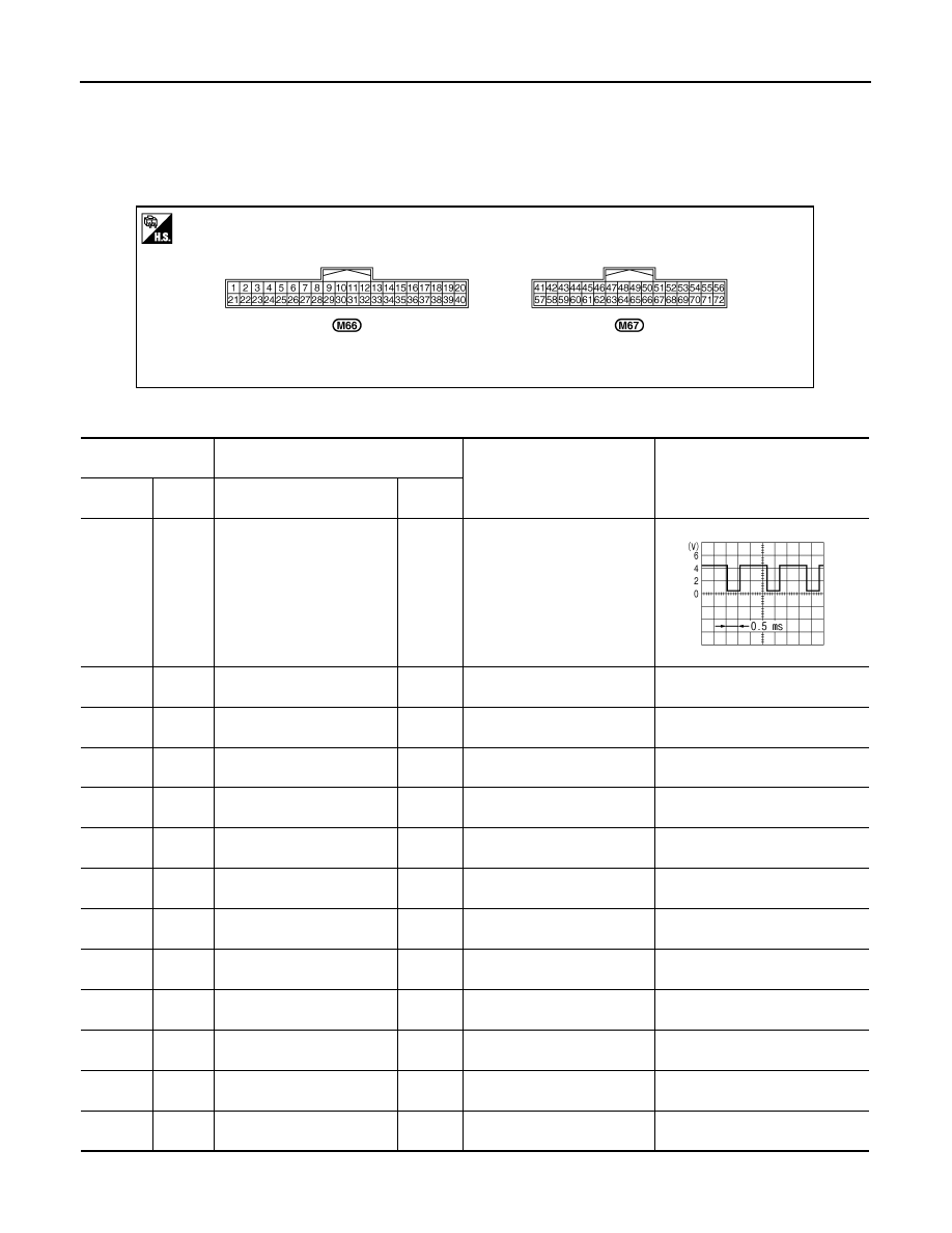
38
(P)
Ground
Blower motor control signal
Output
• Ignition switch ON
• Blower speed: 1st speed
(manual)
41
(V)
Ground
Power supply from ACC
—
Ignition switch ACC
Battery voltage
43
(R)
Ground
Intake sensor
Input
—
—
44
(LG)
Ground
In-vehicle sensor
Input
—
—
45
( P)
Ground
Ambient sensor
Input
—
—
46
(O)
Ground
Sunload sensor
Input
—
—
53
(G)
Ground
Power supply from IGN
—
Ignition switch ON
Battery voltage
54
(Y)
Ground
Power supply from BAT
—
Ignition switch OFF
Battery voltage
55
(B)
Ground
Ground
—
Ignition switch ON
0 V
59
(GR)
Ground
Intake sensor ground
—
—
0 V
60
(L)
Ground
In-vehicle sensor ground
—
Ignition switch ON
0 V
61
( BR)
Ground
Ambient sensor ground
—
Ignition switch ON
0 V
62
(SB)
Ground
Sunload sensor ground
—
Ignition switch ON
0 V
JSIIA0096ZZ
AUTO AMP.
HAC-123
< ECU DIAGNOSIS >
[AUTOMATIC AIR CONDITIONER]
C
D
E
F
G
H
J
K
L
M
A
B
HAC
N
O
P
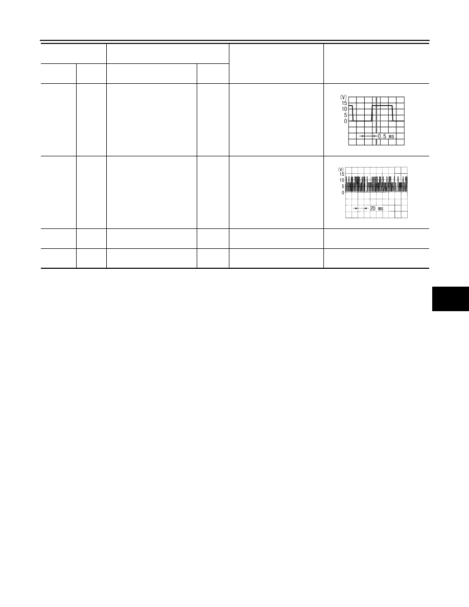
65
(O)
Ground
ECV (Electrical Control
Valve) signal
Output
• Ignition switch ON
• Self-diagnosis. STEP-4
(Code No. 45)
69
(L)
Ground
A/C LAN signal
Input/
Output
Ignition switch ON
70
(R)
Ground
Power supply for each door
motor
Output
Ignition switch ON
Battery voltage
71
( B)
Ground
Ground
—
Ignition switch ON
0 V
Terminal No.
(Wire color)
Description
Condition
Value
(Approx.)
+
−
Signal name
Input/
Output
SJIA1607E
SJIA1453J
Нет комментариевНе стесняйтесь поделиться с нами вашим ценным мнением.
Текст