Infiniti EX35. Manual — part 1492

WCS
METER BUZZER CIRCUIT
WCS-23
< COMPONENT DIAGNOSIS >
C
D
E
F
G
H
I
J
K
L
M
B
A
O
P
METER BUZZER CIRCUIT
Description
INFOID:0000000003135102
• The buzzer for warning chime system is installed in the combination meter.
• The combination meter sounds the alarm buzzer based on the signals transmitted from various units.
Component Function Check
INFOID:0000000003135103
1.
CHECK OPERATION OF METER BUZZER
1.
Select “BUZZER” of “BCM” on CONSULT-III.
2.
Perform “LIGHT WARN ALM” of “ACTIVE TEST”.
Does meter buzzer beep?
YES
>> INSPECTION END
NO
>> GO TO 2.
2.
CHECK UNIFIED METER AND A/C AMP. INPUT SIGNAL
Select the “Data Monitor” for the “METER/M&A” and check the “BUZZER” monitor value.
Is the inspection result normal?
YES
>> Replace combination meter.
NO
>> Replace BCM. Refer to
BCS-84, "Removal and Installation"
Diagnosis Procedure
INFOID:0000000003135104
1.
CHECK POWER SUPPLY OF COMBINATION METER
Check power supply of combination meter. Refer to
WCS-20, "COMBINATION METER : Diagnosis Proce-
.
Is the inspection result normal?
YES
>> GO TO 2.
NO
>> Repair power supply circuit of combination meter.
2.
CHECK POWER SUPPLY OF UNIFIED METER AND A/C AMP.
Check power supply of unified meter and A/C amp. Refer to
WCS-20, "UNIFIED METER AND A/C AMP. :
.
Is the inspection result normal?
YES
>> INSPECTION END
NO
>> Repair power supply circuit of unified meter and A/C amp.
BUZZER
Under the condition of buzzer input
: On
Except above
: Off
WCS-24
< COMPONENT DIAGNOSIS >
SEAT BELT BUCKLE SWITCH SIGNAL CIRCUIT
SEAT BELT BUCKLE SWITCH SIGNAL CIRCUIT
Description
INFOID:0000000003135105
Transmits a seat belt buckle switch signal to the unified meter and A/C amp.
Component Function Check
INFOID:0000000003135106
1.
CHECK UNIFIED METER AND A/C AMP. INPUT SIGNAL
Select the “Data Monitor” for the “METER/M&A” and check the “BUCKLE SW” monitor value.
>> INSPECTION END
Diagnosis Procedure
INFOID:0000000003135107
1.
CHECK UNIFIED METER AND A/C AMP. INPUT SIGNAL
1.
Turn ignition switch ON.
2.
Check voltage between unified meter and A/C amp. harness connector and ground.
Is the inspection result normal?
YES
>> Replace unified meter and A/C amp.
NO
>> GO TO 2.
2.
CHECK SEAT BELT BUCKLE SWITCH CIRCUIT
1.
Turn ignition switch OFF.
2.
Disconnect unified meter and A/C amp. connector and seat belt buckle switch (driver side) connector.
3.
Check continuity between unified meter and A/C amp. harness connector and seat belt buckle switch
(driver side) harness connector.
4.
Check harness continuity between unified meter and A/C amp. harness connector and ground.
Is the inspection result normal?
YES
>> GO TO 3.
NO
>> Repair harness or connector.
3.
CHECK SEAT BELT BUCKLE SWITCH GROUND CIRCUIT
Check harness continuity between seat belt buckle switch (driver side) harness connector and ground.
BUCKLE SW
When seat belt is fastened
: Off
When seat belt is unfastened
: On
Terminals
Condition
Voltage
(Approx.)
(+)
(-)
Unified meter and A/C amp.
Ground
Connector
Terminal
M66
9
When driver seat belt is fastened
12 V
When driver seat belt is unfastened
0 V
Unified meter and A/C amp.
Seat belt buckle switch (driver side)
Continuity
Connector
Terminal
Connector
Terminal
M66
9
B13
1
Existed
Unified meter and A/C amp.
Ground
Continuity
Connector
Terminal
M66
9
Not existed
WCS
SEAT BELT BUCKLE SWITCH SIGNAL CIRCUIT
WCS-25
< COMPONENT DIAGNOSIS >
C
D
E
F
G
H
I
J
K
L
M
B
A
O
P
Is the inspection result normal?
YES
>> INSPECTION END
NO
>> Repair harness or connector.
Component Inspection
INFOID:0000000003135108
1.
CHECK SEAT BELT BUCKLE SWITCH UNIT
1.
Turn ignition switch OFF.
2.
Disconnect the seat belt buckle switch connector.
3.
Check continuity between terminals.
Is the inspection result normal?
YES
>> INSPECTION END
NO
>> Replace the seat belt buckle. Refer to
SB-7, "SEAT BELT BUCKLE : Removal and Installation"
.
Seat belt buckle switch (driver side)
Ground
Continuity
Connector
Terminal
B13
2
Existed
Terminal
Condition
Continuity
1
2
When seat belt is fastened
Not existed
When seat belt is unfastened
Existed
WCS-26
< COMPONENT DIAGNOSIS >
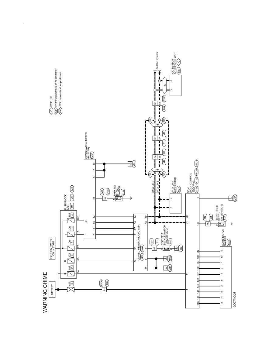
WARNING CHIME SYSTEM
WARNING CHIME SYSTEM
Wiring Diagram - WARNING CHIME -
INFOID:0000000003135109
JCNWM0721GB
Нет комментариевНе стесняйтесь поделиться с нами вашим ценным мнением.
Текст