Infiniti EX35. Manual — part 265
AV
AROUND VIEW MONITOR CONTROL UNIT
AV-841
< ECU DIAGNOSIS >
[BOSE AUDIO WITH NAVIGATION]
C
D
E
F
G
H
I
J
K
L
M
B
A
O
P
21
(W)
—
AV communication signal (H)
Input/
Output
—
—
—
22
(B)
—
AV communication signal (L)
Input/
Output
—
—
—
23
(LG)
24
(G)
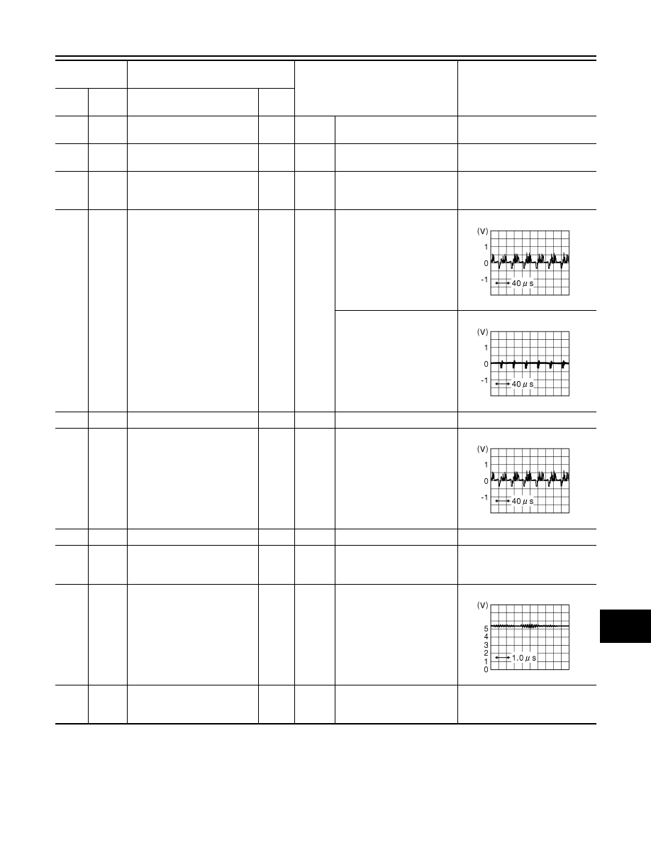
Auxiliary infrared LED power
supply
Output
Ignition
switch
ON
“CAMERA” switch is ON or
shift position is “R”.
5.5 V
27
(W)
Ground
Camera image signal
Output
Ignition
switch
ON
At camera image display
Other than camera image
display
28
—
Camera image ground
—
—
—
—
29
(Y)
30
(G)
Side camera passenger side
image signal
Input
Input
“CAMERA” switch is ON or
shift position is “R”.
31
—
Shield
—
—
—
—
32
(B)
Ground
Side camera passenger side
ground
—
Ignition
switch
ON
—
0 V
33
(W)
Ground
Side camera passenger side
communication signal
Input/
Output
Ignition
switch
ON
“CAMERA” switch is ON or
shift position is “R”.
34
(R)
Ground
Side camera passenger side
power supply
Output
Ignition
switch
ON
“CAMERA” switch is ON or
shift position is “R”.
6.0 V
Terminal
(Wire color)
Description
Condition
Reference value
(Approx.)
+
–
Signal name
Input/
Output
JSNIA0834GB
JSNIA0835GB
JSNIA0834GB
JSNIA0836GB

AV-842
< ECU DIAGNOSIS >
[BOSE AUDIO WITH NAVIGATION]
AROUND VIEW MONITOR CONTROL UNIT
35
(L)
Ground
Rear camera communication
signal
Input/
Output
Ignition
switch
ON
“CAMERA” switch is ON or
shift position is “R”.
36
(BR)
Ground
Rear camera power supply
Output
Ignition
switch
ON
“CAMERA” switch is ON or
shift position is “R”.
6.0 V
37
—
Shield
—
—
—
—
38
(R)
Ground
Rear camera ground
—
Ignition
switch
ON
—
0 V
39
(Y)
40
(W)
Rear camera image signal
Input
Ignition
switch
ON
“CAMERA” switch is ON or
shift position is “R”.
41
(Y)
42
(G)
Front camera image signal
Input
Ignition
switch
ON
“CAMERA” switch is ON or
shift position is “R”.
43
—
Shield
—
—
—
—
44
(B)
Ground
Front camera ground
—
Ignition
switch
ON
—
0 V
45
(W)
Ground
Front camera communication
signal
Input/
Output
Ignition
switch
ON
“CAMERA” switch is ON or
shift position is “R”.
46
(R)
Ground
Front camera power supply
Output
Ignition
switch
ON
“CAMERA” switch is ON or
shift position is “R”.
6.0 V
47
(L)
Ground
Side camera driver side com-
munication signal
Input/
Output
Ignition
switch
ON
“CAMERA” switch is ON or
shift position is “R”.
Terminal
(Wire color)
Description
Condition
Reference value
(Approx.)
+
–
Signal name
Input/
Output
JSNIA0836GB
JSNIA0834GB
JSNIA0834GB
JSNIA0836GB
JSNIA0836GB
AV
AROUND VIEW MONITOR CONTROL UNIT
AV-843
< ECU DIAGNOSIS >
[BOSE AUDIO WITH NAVIGATION]
C
D
E
F
G
H
I
J
K
L
M
B
A
O
P
Wiring Diagram - BOSE AUDIO WITH NAVIGATION AND AROUND VIEW MONITOR
-
INFOID:0000000003737138
Click here to view the eWD.
NOTE:
48
(BR)
Ground
Side camera driver side power
supply
Output
Ignition
switch
ON
“CAMERA” switch is ON or
shift position is “R”.
6.0 V
49
—
Shield
—
—
—
—
50
(R)
Ground
Side camera driver side
ground
—
Ignition
switch
ON
—
0 V
51
(Y)
52
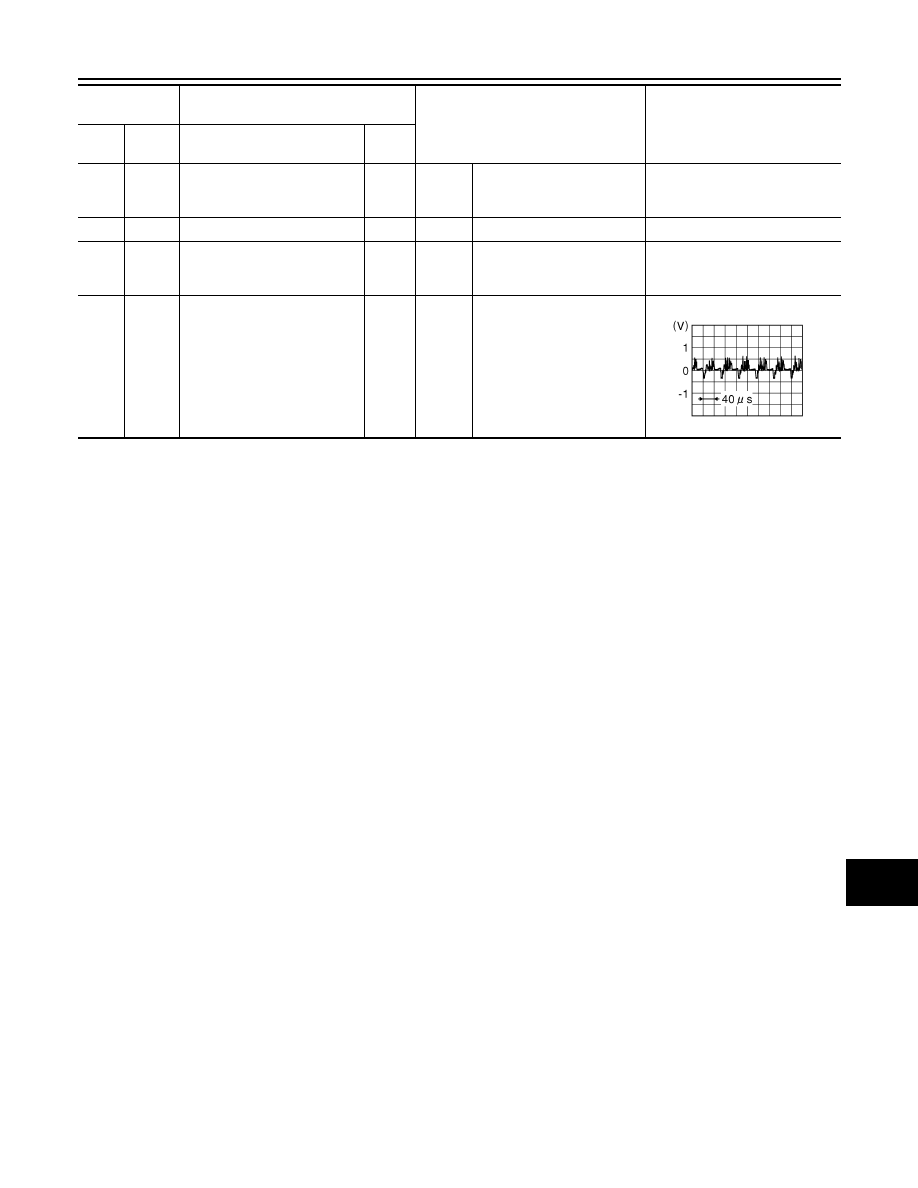
(W)
Side camera driver side image
signal
Input
Ignition
switch
ON
“CAMERA” switch is ON or
shift position is “R”.
Terminal
(Wire color)
Description
Condition
Reference value
(Approx.)
+
–
Signal name
Input/
Output
JSNIA0834GB

AV-844
< ECU DIAGNOSIS >
[BOSE AUDIO WITH NAVIGATION]
AROUND VIEW MONITOR CONTROL UNIT
The name MULTIFUNCTION SWITCH indicates the integration of PRESET SWITCH and MULTIFUNCTION
SWITCH virtually.
JCNWM0793GB
Нет комментариевНе стесняйтесь поделиться с нами вашим ценным мнением.
Текст