Infiniti EX35. Manual — part 851

FL-2
< PRECAUTION >
PRECAUTIONS
PRECAUTION
PRECAUTIONS
General Precautions
INFOID:0000000003136985
WARNING:
When replacing fuel line parts, be sure to observe the following.
• Put a “CAUTION: FLAMMABLE” sign in the workshop.
• Be sure to work in a well ventilated area and furnish workshop with a CO
2
fire extinguisher.
• Never smoke while servicing fuel system. Keep open flames and sparks away from the work area.
CAUTION:
• Use gasoline required by the regulations for octane number. Refer to
• Before removing fuel line parts, perform out the following procedures:
- Put drained fuel in an explosion-proof container and put the lid on securely. Keep the container in
safe area.
- Release fuel pressure from the fuel lines. Refer to
- Disconnect the battery cable from the negative terminal.
• Always replace O-ring and clamps with new ones.
• Never kink or twist tubes when they are being installed.
• Never tighten hose clamps excessively to avoid damaging hoses.
• After installing tubes, check there is no fuel leakage at connections in the following steps.
- Apply fuel pressure to fuel lines with turning ignition switch “ON” (with engine stopped). Then check
for fuel leakage at connections.
- Start engine and rev it up and check for fuel leakage at connections.
• Use only a genuine NISSAN fuel filler cap as a replacement. If an incorrect fuel filler cap is used, the
“MIL” may come on.
• For servicing “Evaporative Emission System” parts, refer to
.
• For servicing “On Board Refueling Vapor Recovery (ORVR)” parts, refer to
.
PREPARATION
FL-3
< PREPARATION >
C
D
E
F
G
H
I
J
K
L
M
A
FL
N
P
O
PREPARATION
PREPARATION
Commercial Service Tools
INFOID:0000000003136986
Tool name
Description
Power tool
Loosening bolts and nuts
PBIC0190E
FL-4
< ON-VEHICLE MAINTENANCE >
FUEL SYSTEM
ON-VEHICLE MAINTENANCE
FUEL SYSTEM
Inspection
INFOID:0000000003136987
• Inspect fuel lines, fuel filler cap and fuel tank for improper attach-
ment, leakage, cracks, damage, loose connections, chafing or
deterioration.
• If necessary, repair or replace damaged parts.
Quick Connector
INFOID:0000000003136988
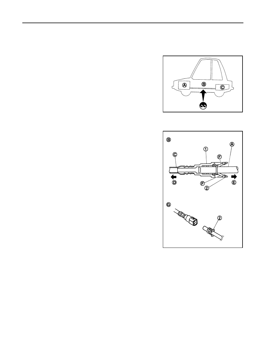
CAUTION:
• After connecting fuel tube quick connectors, check quick con-
nectors are secure.
• Ensure that connector and resin tube never contact any adja-
cent parts.
A
: Engine
B
: Fuel line
C
: Fuel tank
JPBIA0129ZZ
1
: Quick connector
2
: Retainer
A
: Hard tube (or the equivalent)
B
: Connection (cross-section)
C
: Resin tube
D
: To under floor fuel line
E
: To fuel tank
F
: Tab
G
: Disconnection
JPBIA0130ZZ

FUEL LEVEL SENSOR UNIT, FUEL FILTER AND FUEL PUMP ASSEMBLY
FL-5
< ON-VEHICLE REPAIR >
C
D
E
F
G
H
I
J
K
L
M
A
FL
N
P
O
ON-VEHICLE REPAIR
FUEL LEVEL SENSOR UNIT, FUEL FILTER AND FUEL PUMP ASSEMBLY
Exploded View
INFOID:0000000003136989
Removal and Installation
INFOID:0000000003136990
WARNING:
Read “General Precautions” when working on the fuel system. Refer to
.
REMOVAL
1.
Check fuel level on fuel gauge. If fuel gauge indicates more than
the level as shown in the figure (full or almost full), drain fuel
from fuel tank until fuel gauge indicates level as shown in the fig-
ure or below.
NOTE:
Because fuel will be spilled when removing main and sub fuel
level sensor units for the top of the fuel is above the main and
sub fuel level sensor units installation surface.
• As a guide, fuel level becomes the position as shown in the
figure or below when approximately 20 (5-1/4 US gal, 4-3/8
Imp gal) of fuel are drained from fuel tank.
• In a case that fuel pump does not operate, perform the follow-
ing procedure.
1.
Retainer
2.
Main fuel level sensor unit, fuel filter
and fuel pump assembly
3.
O-ring
4.
Sub fuel level sensor unit
A.
Right side
B.
Left side
Refer to
JPBIA1835GB
JPBIA0131ZZ
Нет комментариевНе стесняйтесь поделиться с нами вашим ценным мнением.
Текст