Infiniti EX35. Manual — part 943
INTERIOR ROOM LAMP BATTERY SAVER SYSTEM
INL-9
< FUNCTION DIAGNOSIS >
C
D
E
F
G
H
I
J
K
M
A
B
INL
N
O
P
INTERIOR ROOM LAMP BATTERY SAVER SYSTEM
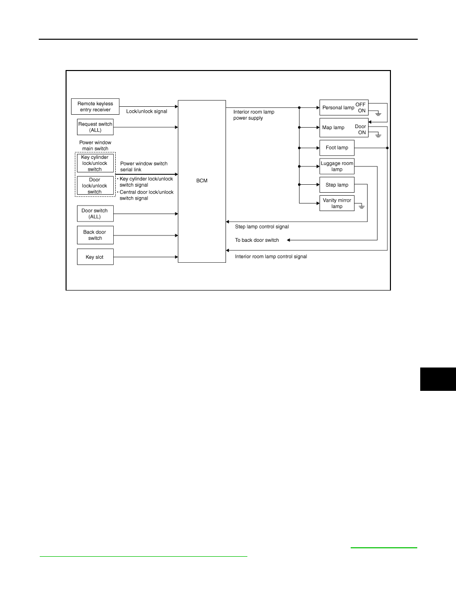
System Diagram
INFOID:0000000003562627
System Description
INFOID:0000000003562628
OUTLINE
• Interior room lamp battery saver is controlled by BCM.
• BCM turns applicable lamps OFF depending on the vehicle condition. This function prevents the battery
from over-discharging if the driver neglect turning OFF the any lamps.
Applicable lamps
• Map lamp
• Foot lamp
• Personal lamp
• Step lamp
• Luggage room lamp
• Vanity mirror lamp
INTERIOR ROOM LAMP BATTERY SAVER FUNCTION
• When the ignition switch is turned OFF, BCM operates the timer for a period of time to cut the interior room
lamp power supply.
• BCM restart the timer when any of the following signals changes while operating the timer.
- Ignition switch status
- Door switch signal (ALL)
- Door lock/unlock signal (Remote keyless entry receiver, each request switch, key cylinder lock/unlock
switch, door lock/unlock switch)
- Back door switch signal
- Key switch signal (Key slot)
• BCM provides the interior room lamp power supply continuously when the ignition switch position is other
than OFF.
NOTE:
Each function of interior room lamp battery saver can be set by CONSULT-III Refer to
SAVER : CONSULT-III Function (BCM - BATTERY SAVER)"
JPLIA0854GB
INL-10
< FUNCTION DIAGNOSIS >
INTERIOR ROOM LAMP BATTERY SAVER SYSTEM
Component Parts Location
INFOID:0000000003562629
1.
Personal lamp
2.
Request switch
3.
Step lamp
4.
Door switch
5.
Luggage room lamp (luggage side)
6.
Key cylinder lock/unlock switch
7.
Push-button ignition switch
8.
Map lamp
9.
Vanity mirror lamp
10. Door lock/unlock switch
11.
Foot lamp
12.
Key slot
13. BCM
14.
Remote keyless entry receiver
15.
Luggage room lamp (back door side)
16. Back door switch
A.
Dash side lower (passenger side)
B.
Over the glove box
C.
Back door
D.
Back door lock assembly
JPLIA0950ZZ

INTERIOR ROOM LAMP BATTERY SAVER SYSTEM
INL-11
< FUNCTION DIAGNOSIS >
C
D
E
F
G
H
I
J
K
M
A
B
INL
N
O
P
Component Description
INFOID:0000000003562630
Part
Description
BCM
Operates the interior room lamp battery saver depending on the vehicle condition to
cut the interior room lamp power supply.
Remote keyless entry receiver
• Receives the lock/unlock signal from keyfob.
• Transmits the lock/unlock signal to BCM.
• Request switch
• Key cylinder lock/unlock switch
• Door lock/unlock switch
Inputs the lock/unlock signal to BCM.
• Door switch
• Back door switch
Inputs a switch signal to BCM.
Key slot
Inputs the key switch status to BCM.
INL-12
< FUNCTION DIAGNOSIS >
ILLUMINATION CONTROL SYSTEM
ILLUMINATION CONTROL SYSTEM
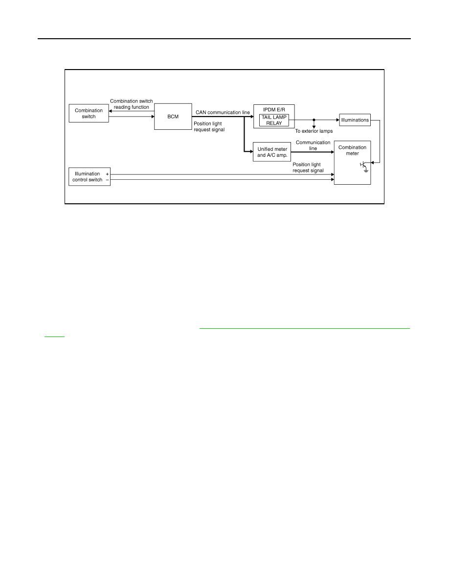
System Diagram
INFOID:0000000003762585
System Description
INFOID:0000000003762586
OUTLINE
Each illumination lamp is controlled by each function of BCM, IPDM E/R and combination meter.
Control by BCM
• Combination switch reading function
• Headlamp control function
Control by IPDM E/R
• Relay control function
Control by combination meter
• Meter illumination control function (Refer to
MWI-26, "METER ILLUMINATION CONTROL : System Dia-
.)
ILLUMINATION CONTROL
• BCM detects the combination switch condition by the combination switch reading function.
• BCM transmits position light request signal to IPDM E/R and combination meter (through the unified meter
and A/C amp.) according to tail lamp ON condition.
Tail lamp ON condition
- Lighting switch 1ST
- Lighting switch 2ND
- Lighting switch AUTO, and the auto light function ON judgment (With auto light system)
• IPDM E/R turns the integrated tail lamp relay ON according to position light request signal. It provides the
power supply to each illumination lamp.
• Combination meter enters in the nighttime mode according to position light request signal (through the uni-
fied meter and A/C amp.). Under the nighttime mode the combination meter controls the illuminance by con-
trolling the each illumination lamp (ground side).
JPLIA0092GB
Нет комментариевНе стесняйтесь поделиться с нами вашим ценным мнением.
Текст