Infiniti EX35. Manual — part 1402
STR-14
< PREPARATION >
PREPARATION
PREPARATION
PREPARATION
Special Service Tools
INFOID:0000000003131858
Commercial Service Tools
INFOID:0000000003131859
Tool number
(Kent-Moore No.)
Tool name
Description
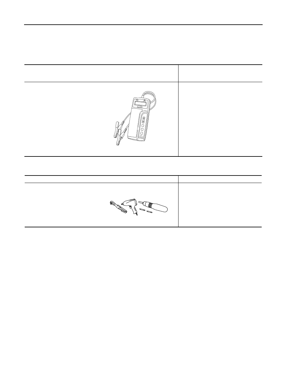
—
(J-44373 Model MCR620)
Starting/Charging System Tester
Tests starting and charging systems.
For operating instructions, refer to Technical
Service Bulletin.
SEL403X
Tool name
Description
Power tool
Loosening bolts, nuts and screws
PIIB1407E
STARTER MOTOR
STR-15
< ON-VEHICLE REPAIR >
C
D
E
F
G
H
I
J
K
L
M
A
STR
N
P
O
ON-VEHICLE REPAIR
STARTER MOTOR
Exploded View
INFOID:0000000003131860
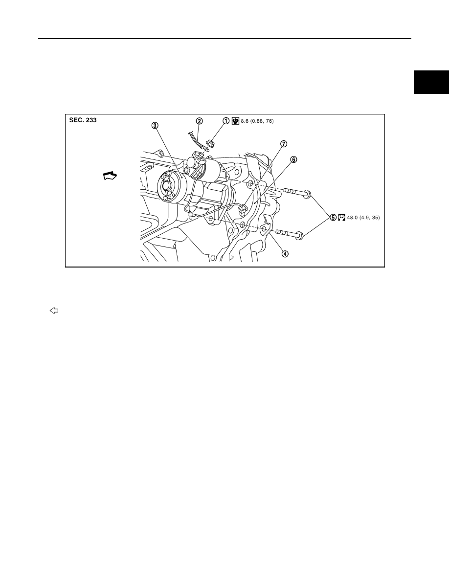
REMOVAL
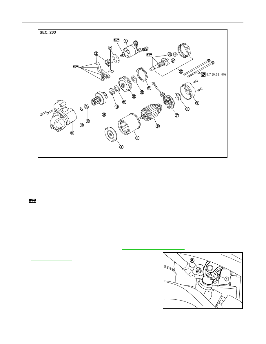
DISASSEMBLY
Type: S114-927
1.
“B” terminal nut
2.
“B” terminal harness
3.
Starter motor
4.
Harness clip bracket
5.
Starter motor mounting bolt
6.
Converter housing
7.
“S” connector
: Engine front
Refer to
JPBIA0147GB
STR-16
< ON-VEHICLE REPAIR >
STARTER MOTOR
Removal and Installation
INFOID:0000000003131861
REMOVAL
1.
Disconnect the battery cable from the negative terminal.
2.
Remove engine undercover, using power tools.
3.
Remove exhaust mounting bracket. Refer to
.
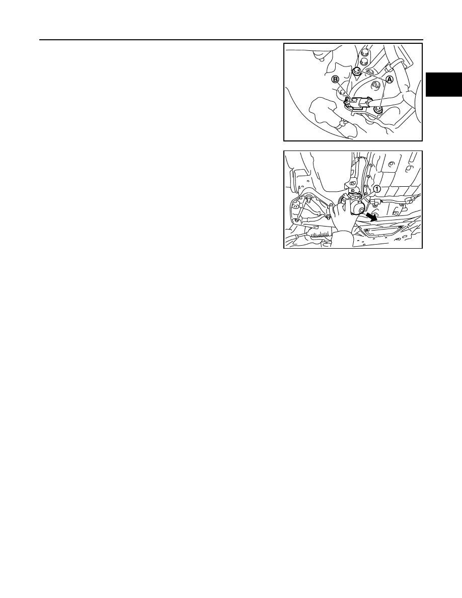
4.
Disconnect steering lower joint (1), then remove it. Refer to
5.
Remove “B” terminal nut (A).
1.
Magnetic switch assembly
2.
Dust cover kit
3.
Shift lever set
4.
Center bracket (A)
5.
Yoke assembly
6.
Armature assembly
7.
Brush holder assembly
8.
Thrust washer
9.
Rear cover assembly
10. Shaft gear assembly
11.
Packing
12. Thrust washer
13. Center bracket (P)
14. E-ring
15. Pinion assembly
16. Pinion stopper
17. Pinion stopper clip
18. Gear case assembly
: High-temperature grease point
Refer to
for symbols not described on the above.
JPBIA0148GB
JSBIA0003ZZ
STARTER MOTOR
STR-17
< ON-VEHICLE REPAIR >
C
D
E
F
G
H
I
J
K
L
M
A
STR
N
P
O
6.
Disconnect “S” connector (B).
7.
Remove starter motor mounting bolts (A), using power tools.
8.
Remove starter motor (1) downward from the vehicle.
INSTALLATION
Install in the reverse order of removal.
CAUTION:
Be sure to tighten “B” terminal nut carefully.
Inspection
INFOID:0000000003131862
INSPECTION AFTER DISASSEMBLY
Pinion/Clutch Check
1.
Inspect pinion teeth.
• Replace pinion if teeth are worn or damaged. (Also check condition of ring gear teeth.)
2.
Inspect reduction gear teeth.
• Replace reduction gear if teeth are worn or damaged. (Also check condition of armature shaft gear
teeth.)
3.
Check to see if pinion locks in one direction and rotates smoothly in the opposite direction.
• If it locks or rotates in both directions, or unusual resistance is evident, replace.
JSBIA0004ZZ
JSBIA0002ZZ
Нет комментариевНе стесняйтесь поделиться с нами вашим ценным мнением.
Текст