Infiniti EX35. Manual — part 1478
VTL-30
< ON-VEHICLE REPAIR >
INTAKE SENSOR
Removal and Installation
INFOID:0000000003545409
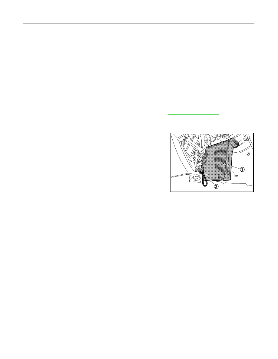
REMOVAL
1.
Remove low-pressure pipe 1 and high-pressure pipe 2. Refer to
CAUTION:
Cap or wrap the joint of the A/C piping with suitable material such as vinyl tape to avoid the entry
of air.
2.
Slide evaporator (1) to passenger side, and then remove intake
sensor (2).
INSTALLATION
Installation is basically the reverse order of removal.
CAUTION:
• Replace O-rings with new ones. Then apply compressor oil to them when installing.
• Mark the mounting position of intake sensor bracket prior to removal so that the reinstalled sensor
can be located in the same position.
• Female-side piping connection is thin and easy to deform. Slowly insert the male-side piping
straight in axial direction.
• Insert piping securely until a click is heard.
• After piping connection is completed, pull male-side piping by hand to make sure that connection
does not come loose.
• Check for leakages when recharging refrigerant.
37. J-nut
38.
Front heater duct
39.
Aspirator hose
40. Aspirator
41.
Foot duct (left)
42.
Defroster door (left)
43. Packing
44.
Center case
45.
Foot door (left)
46. Rear ventilator door
47.
Foot door (right)
48.
J-nut
49. Max. cool door lever
50.
Defroster door lever
51.
Defroster door link
52. Max. cool door link
53.
Intake sensor
54.
Intake sensor bracket
55. Air mix door motor (passenger side)
56.
Air mix door adapter
57.
Heater & cooling unit case (right)
58. Max. cool door (right)
59.
Max. cool door (left)
60.
Air mix door (Slide door)
*With left and right ventilation temperature separately system.
for symbols in the figure.
JPIIA0650ZZ
BLOWER UNIT
VTL-31
< ON-VEHICLE REPAIR >
C
D
E
F
G
H
J
K
L
M
A
B
VTL
N
O
P
BLOWER UNIT
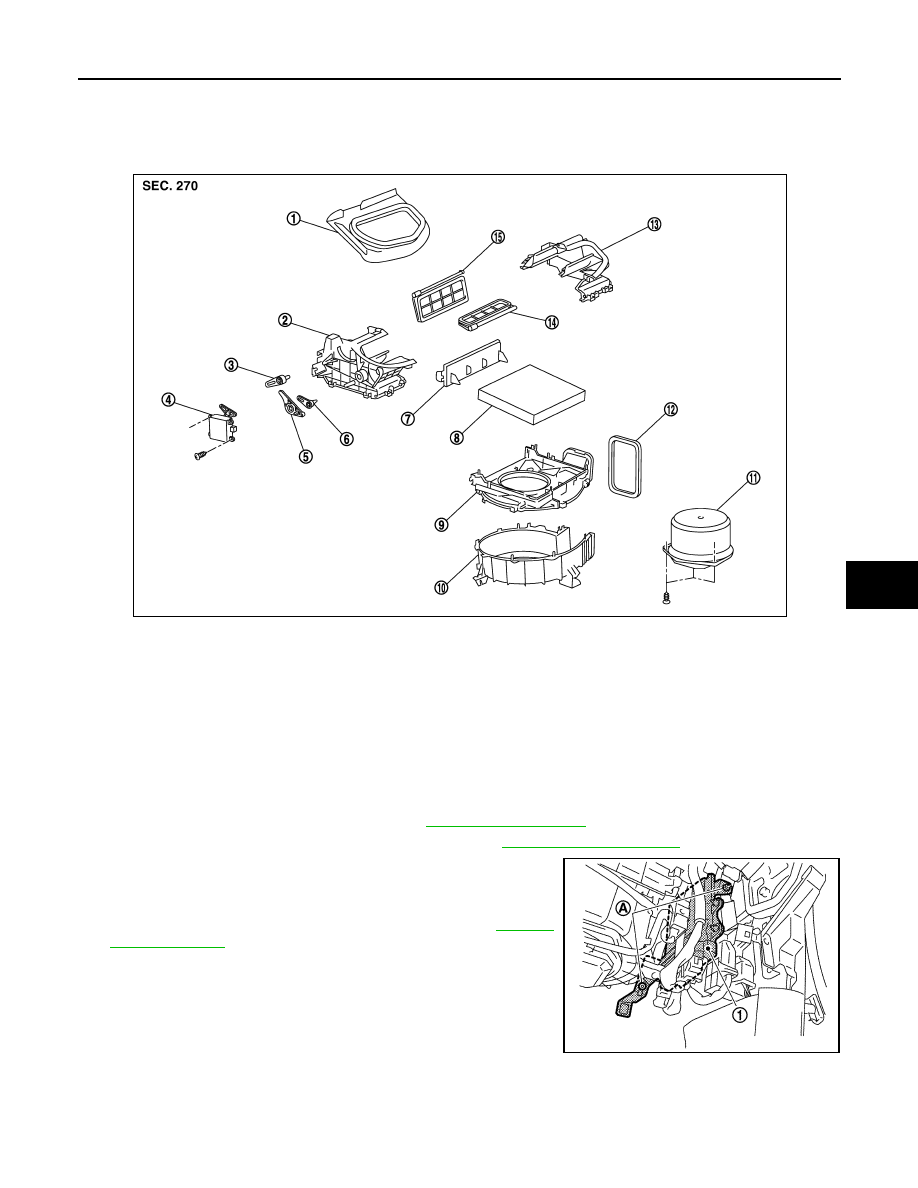
Exploded View
INFOID:0000000003545410
Removal and Installation
INFOID:0000000003545411
REMOVAL
1.
Remove instrument lower panel RH. Refer to
.
2.
Disconnect AWD control unit connector (AWD). Refer to
3.
Disconnect ECM (1) connectors.
4.
Remove mounting nuts (A), and then remove ECM with bracket
attached.
5.
Remove power steering control unit. Refer to
6.
Disconnect intake door motor connector and blower motor connector.
1.
Adapter
2.
Intake box (right)
3.
Intake door lever 2
4.
Intake door motor
5.
Intake door link
6.
Intake door lever 1
7.
Filter cover
8.
In-cabin microfilter
9.
Intake upper case
10. Intake lower case
11.
Blower motor assembly
12. Seal
13. Intake box (left)
14.
Intake door 1
15. Intake door 2
JSIIA0009ZZ
JPIIA0651ZZ

VTL-32
< ON-VEHICLE REPAIR >
BLOWER UNIT
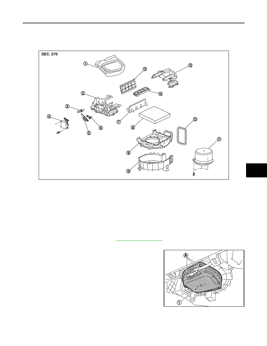
7.
Remove mounting bolt (A) and screw (B), from blower unit (1).
8.
Remove blower unit.
CAUTION:
Move blower unit rightward, and remove locating pin (1
part) and joint. Then remove blower unit downward.
INSTALLATION
Installation is basically the reverse order of removal.
CAUTION:
Make sure locating pin (A) and joint (B) are securely inserted.
JPIIA0652ZZ
:
Vehicle front
JSIIA0008ZZ
BLOWER MOTOR
VTL-33
< ON-VEHICLE REPAIR >
C
D
E
F
G
H
J
K
L
M
A
B
VTL
N
O
P
BLOWER MOTOR
Exploded View
INFOID:0000000003545412
Removal and Installation
INFOID:0000000003545413
REMOVAL
1.
Remove instrument lower cover. Refer to
2.
Disconnect blower motor connector.
3.
Remove mounting screws (A), and then remove blower motor
(1).
INSTALLATION
Installation is basically the reverse order of removal.
1.
Adapter
2.
Intake box (right)
3.
Intake door lever 2
4.
Intake door motor
5.
Intake door link
6.
Intake door lever 1
7.
Filter cover
8.
In-cabin microfilter
9.
Intake upper case
10. Intake lower case
11.
Blower motor assembly
12. Seal
13. Intake box (left)
14.
Intake door 1
15. Intake door 2
JSIIA0009ZZ
JPIIA0653ZZ
Нет комментариевНе стесняйтесь поделиться с нами вашим ценным мнением.
Текст