Infiniti EX35. Manual — part 1115

MWI-138
< ECU DIAGNOSIS >
IPDM E/R (INTELLIGENT POWER DISTRIBUTION MODULE ENGINE ROOM)
IPDM E/R (INTELLIGENT POWER DISTRIBUTION MODULE ENGINE
ROOM)
Reference Value
INFOID:0000000003777653
VALUES ON THE DIAGNOSIS TOOL
Monitor Item
Condition
Value/Status
RAD FAN REQ
Engine idle speed
Changes depending on engine
coolant temperature, air conditioner
operation status, vehicle speed,
etc.
0 – 100 %
AC COMP REQ
Engine running
A/C switch OFF
Off
A/C switch ON
(Compressor is operating)
On
TAIL&CLR REQ
Lighting switch OFF
Off
Lighting switch 1ST, 2ND, HI or AUTO (Light is illuminated)
On
HL LO REQ
Lighting switch OFF
Off
Lighting switch 2ND HI or AUTO (Light is illuminated)
On
HL HI REQ
Lighting switch OFF
Off
Lighting switch HI
On
FR FOG REQ
Lighting switch 2ND or
AUTO (Light is illuminated)
Front fog lamp switch OFF
Off
• Front fog lamp switch ON
• Daytime running light activated
(Only for Canada)
On
FR WIP REQ
Ignition switch ON
Front wiper switch OFF
Stop
Front wiper switch INT
1LOW
Front wiper switch LO
Low
Front wiper switch HI
Hi
WIP AUTO STOP
Ignition switch ON
Front wiper stop position
STOP P
Any position other than front wiper
stop position
ACT P
WIP PROT
Ignition switch ON
Front wiper operates normally
Off
Front wiper stops at fail-safe opera-
tion
BLOCK
IGN RLY1 -REQ
Ignition switch OFF or ACC
Off
Ignition switch ON
On
IGN RLY
Ignition switch OFF or ACC
Off
Ignition switch ON
On
PUSH SW
Release the push-button ignition switch
Off
Press the push-button ignition switch
On
INTER/NP SW
Ignition switch ON
Selector lever in any position other
than P or N
Off
Selector lever in P or N position
On
ST RLY CONT
Ignition switch ON
Off
At engine cranking
On
IHBT RLY -REQ
Ignition switch ON
Off
At engine cranking
On

MWI
IPDM E/R (INTELLIGENT POWER DISTRIBUTION MODULE ENGINE ROOM)
MWI-139
< ECU DIAGNOSIS >
C
D
E
F
G
H
I
J
K
L
M
B
A
O
P
ST/INHI RLY
Ignition switch ON
Off
At engine cranking
INHI
→
ST
The status of starter relay or starter control relay cannot be recognized by
the battery voltage malfunction, etc. when the starter relay is ON and the
starter control relay is OFF
UNKWN
DETENT SW
Ignition switch ON
• Press the selector button with se-
lector lever in P position
• Selector lever in any position oth-
er than P
Off
Release the selector button with selector lever in P position
On
S/L RLY -REQ
None of the conditions below are present
Off
• Open the driver door after the ignition switch is turned OFF (for a few
seconds)
• Press the push-button ignition switch when the steering lock is activat-
ed
On
S/L STATE
Steering lock is activated
LOCK
Steering lock is deactivated
UNLOCK
[DTC: B210A] is detected
UNKWN
DTRL REQ
NOTE:
The item is indicated, but not monitored.
Off
OIL P SW
Ignition switch OFF, ACC or engine running
Open
Ignition switch ON
Close
HOOD SW
Close the hood
Off
Open the hood
On
HL WASHER REQ
NOTE:
The item is indicated, but not monitored.
Off
THFT HRN REQ
Not operation
Off
• Panic alarm is activated
• Horn is activated with VEHICLE SECURITY (THEFT WARNING) SYS-
TEM
On
HORN CHIRP
Not operating
Off
Door locking with Intelligent Key (horn chirp mode)
On
CRNRNG LMP REQ
NOTE:
The item is indicated, but not monitored.
Off
Monitor Item
Condition
Value/Status
MWI-140
< ECU DIAGNOSIS >
IPDM E/R (INTELLIGENT POWER DISTRIBUTION MODULE ENGINE ROOM)
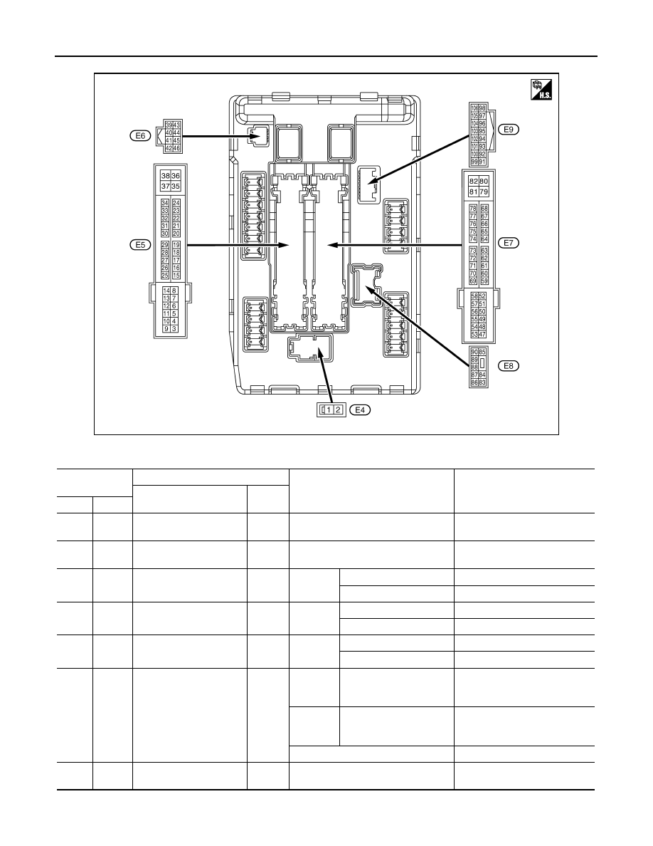
TERMINAL LAYOUT
PHYSICAL VALUES
JSMIA0001ZZ
Terminal No.
(Wire color)
Description
Condition
Value
(Approx.)
Signal name
Input/
Output
+
−
1
(W)
Ground
Battery power supply
Input
Ignition switch OFF
Battery voltage
2
(L)
Ground
Battery power supply
Input
Ignition switch OFF
Battery voltage
4
(V)
Ground
Front wiper LO
Output
Ignition
switch ON
Front wiper switch OFF
0 V
Front wiper switch LO
Battery voltage
5
(L)
Ground
Front wiper HI
Output
Ignition
switch ON
Front wiper switch OFF
0 V
Front wiper switch HI
Battery voltage
7
(R)
Ground
Tail, license plate lamps &
interior lamps
Output
Ignition
switch ON
Lighting switch OFF
0 V
Lighting switch 1ST
Battery voltage
11
(BR)
Ground
Steering lock unit power
supply
Output
Ignition
switch
OFF
A few seconds after open-
ing the driver door
Battery voltage
Ignition
switch
LOCK
Press the push-button ig-
nition switch
Battery voltage
Ignition switch ACC or ON
0 V
12
(B/W)
Ground
Ground
—
Ignition switch ON
0 V

MWI
IPDM E/R (INTELLIGENT POWER DISTRIBUTION MODULE ENGINE ROOM)
MWI-141
< ECU DIAGNOSIS >
C
D
E
F
G
H
I
J
K
L
M
B
A
O
P
13
(SB)
Ground
Fuel pump power supply
Output
Approximately 1 second or more after
turning the ignition switch ON
0 V
• Approximately 1 second after turning
the ignition switch ON
• Engine running
Battery voltage
16
(LG)
Ground
Front wiper auto stop
Input
Ignition
switch ON
Front wiper stop position
0 V
Any position other than
front wiper stop position
Battery voltage
19
(W)
Ground
Ignition relay power supply
Output
Ignition switch OFF
0 V
Ignition switch ON
Battery voltage
25
(G)
Ground
Ignition relay power supply
Output
Ignition switch OFF
0 V
Ignition switch ON
Battery voltage
26*
(R)
Ground
Ignition relay power supply
Output
Ignition switch OFF
0 V
Ignition switch ON
Battery voltage
27
(O)
Ground
Ignition relay monitor
Input
Ignition switch OFF or ACC
Battery voltage
Ignition switch ON
0 V
28
(L)
Ground
Push-button ignition
switch
Input
Press the push-button ignition switch
0 V
Release the push-button ignition switch
Battery voltage
30
(GR)
Ground
Starter relay control
Input
Ignition
switch ON
Selector lever in any posi-
tion other than P or N
0 V
Selector lever P or N
Battery voltage
32
(L)
Ground
Steering lock unit condi-
tion-1
Input
Steering lock is activated
0 V
Steering lock is deactivated
Battery voltage
33
(P)
Ground
Steering lock unit condi-
tion-2
Input
Steering lock is activated
Battery voltage
Steering lock is deactivated
0 V
36
(G)
Ground
Battery power supply
Input
Ignition switch OFF
Battery voltage
39
(P)
—
CAN-L
Input/
Output
—
—
40
(L)
—
CAN-H
Input/
Output
—
—
41
(B/W)
Ground
Ground
—
Ignition switch ON
0 V
42
(Y)
Ground
Cooling fan relay control
Input
Ignition switch OFF or ACC
0 V
Ignition switch ON
0.7 V
43
(SB)
Ground
Control device
(Detention switch)
Input
Ignition
switch ON
• Press the selector but-
ton (Selector lever P)
• Selector lever in any po-
sition other than P
Battery voltage
Release the selector but-
ton (selector lever P)
0 V
44
(W)
Ground
Horn relay control
Input
The horn is deactivated
Battery voltage
The horn is activated
0 V
45
(G)
Ground
Anti theft horn relay control
Input
The horn is deactivated
Battery voltage
The horn is activated
0 V
Terminal No.
(Wire color)
Description
Condition
Value
(Approx.)
Signal name
Input/
Output
+
−
Нет комментариевНе стесняйтесь поделиться с нами вашим ценным мнением.
Текст