Infiniti EX35. Manual — part 962
COMBINATION METER
INL-85
< ECU DIAGNOSIS >
C
D
E
F
G
H
I
J
K
M
A
B
INL
N
O
P
COMBINATION METER
Reference Value
INFOID:0000000003757121
VALUES ON THE DIAGNOSIS TOOL
.
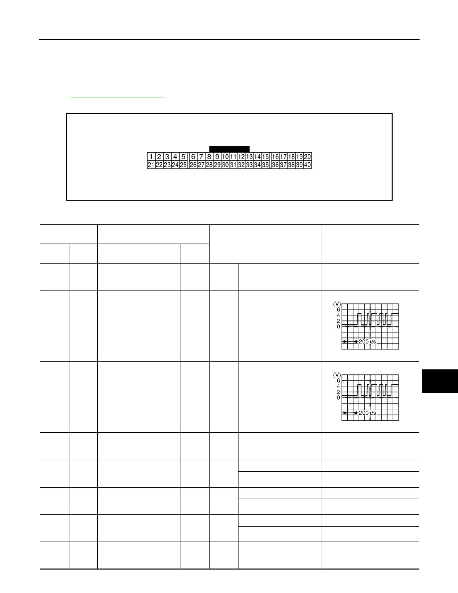
TERMINAL LAYOUT
PHYSICAL VALUES
JSNIA0457ZZ
Terminal No.
(Wire color)
Description
Condition
Value
(Approx.)
+
–
Signal name
Input/
Output
1
(GR)
Ground
Battery power supply
Input
Ignition
switch
OFF
—
Battery voltage
2
(LG)
Ground
Communication signal
(METER
→
AMP.)
Output
Ignition
switch
ON
—
3
(GR)
Ground
Communication signal
(AMP.
→
METER)
Input
Ignition
switch
ON
—
5
(B)
Ground
Ground
—
Ignition
switch
ON
—
0 V
6
(P)
Ground
Alternator signal
Input
Ignition
switch
ON
Charge warning lamp ON
0 V
Charge warning lamp OFF
Battery voltage
7
(LG)
Ground
Air bag signal
Input
Ignition
switch
ON
Air bag warning lamp ON
4 V
Air bag warning lamp OFF
0 V
10
(G)
Ground
Security signal
Input
Ignition
switch
OFF
Security warning lamp ON
0 V
Security warning lamp OFF
12 V
15
(B)
Ground
Ground
—
Ignition
switch
ON
—
0 V
JSNIA0027GB
JSNIA0027GB
INL-86
< ECU DIAGNOSIS >
COMBINATION METER
16
(B)
Ground
Meter control switch ground
—
Ignition
switch
ON
—
0 V
21
(O)
Ground
Ignition signal
Input
Ignition
switch
ON
—
Battery voltage
22
(B)
Ground
Ground
—
Ignition
switch
ON
—
0 V
23
(L)
Ground
ACC power supply
Input
Ignition
switch
ACC
—
Battery voltage
24
(BR)
Ground
Communication signal
(LCD
→
AMP.)
Output
Ignition
switch
ON
—
25
(Y)
Ground
Communication signal
(AMP.
→
LCD)
Input
Ignition
switch
ON
—
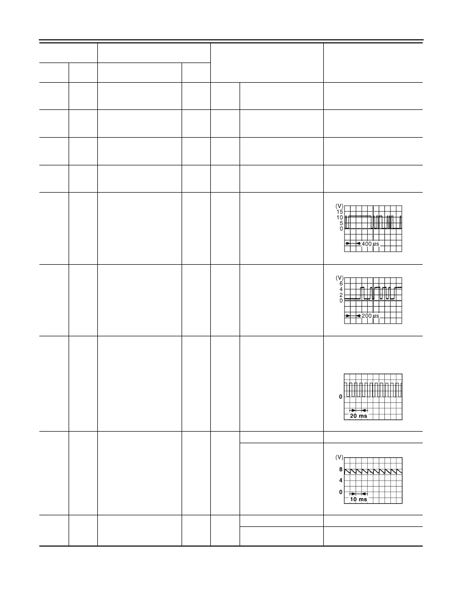
26
(R)
Ground
Vehicle speed signal
(8-pulse)
Input
Ignition
switch
ON
Speedometer operated
[When vehicle speed is ap-
prox. 40 km/h (25 MPH)]
NOTE:
The maximum voltage varies de-
pending on the specification
(destination unit).
27
(V)
Ground
Parking brake switch signal
Input
Ignition
switch
ON
Parking brake ON
0 V
Parking brake OFF
28
(W)
Ground
Brake fluid level switch sig-
nal
Input
Ignition
switch
ON
Brake fluid level is normal.
5 V
The brake fluid level is low-
er than the low level
0 V
Terminal No.
(Wire color)
Description
Condition
Value
(Approx.)
+
–
Signal name
Input/
Output
JSNIA0028GB
JSNIA0027GB
JSNIA0012GB
JSNIA0007GB
COMBINATION METER
INL-87
< ECU DIAGNOSIS >
C
D
E
F
G
H
I
J
K
M
A
B
INL
N
O
P
29
(SB)
Ground
Seat belt buckle switch sig-
nal (driver side)
Input
Ignition
switch
ON
When driver seat belt is fas-
tened
12 V
When driver seat belt is un-
fastened
0 V
30
(G)
Ground
Seat belt buckle switch sig-
nal (passenger side)
Input
Ignition
switch
ON
• When getting in the pas-
senger seat
• When passenger seat
belt is fastened
12 V
• When getting in the pas-
senger seat
• When passenger seat
belt is unfastened
0 V
31
(L)
Ground
Washer level switch signal
Input
Ignition
switch
ON
Washer level switch ON
0 V
Washer level switch OFF
5 V
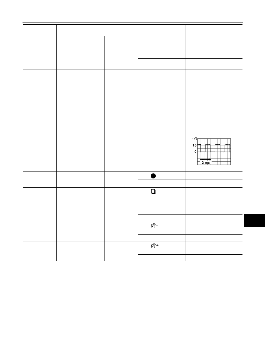
33
(B)
Ground
Illumination control signal
Output
Ignition
switch
ON
Lighting switch ON, then
operate the illumination
control switch.
NOTE:
When brightness level is midway
36
(LG)
16
(B)
Select switch signal
Input
Ignition
switch
ON
When
is
pressed
0 V
Other than the above
5 V
37
(SB)
16
(B)
Enter switch signal
Input
Ignition
switch
ON
When
is pressed
0 V
Other than the above
5 V
38
(L)
16
(B)
Trip A/B reset switch signal
Input
Ignition
switch
ON
When trip A/B reset switch
is pressed
0 V
Other than the above
5 V
39
(P)
16
(B)
Illumination control switch
signal (–)
Input
Ignition
switch
ON
When
switch is
pressed
0 V
Other than the above
5 V
40
(O)
16
(B)
Illumination control switch
signal (+)
Input
Ignition
switch
ON
When
switch
is
pressed
0 V
Other than the above
5 V
Terminal No.
(Wire color)
Description
Condition
Value
(Approx.)
+
–
Signal name
Input/
Output
JSNIA0010GB
INL-88
< ECU DIAGNOSIS >
COMBINATION METER
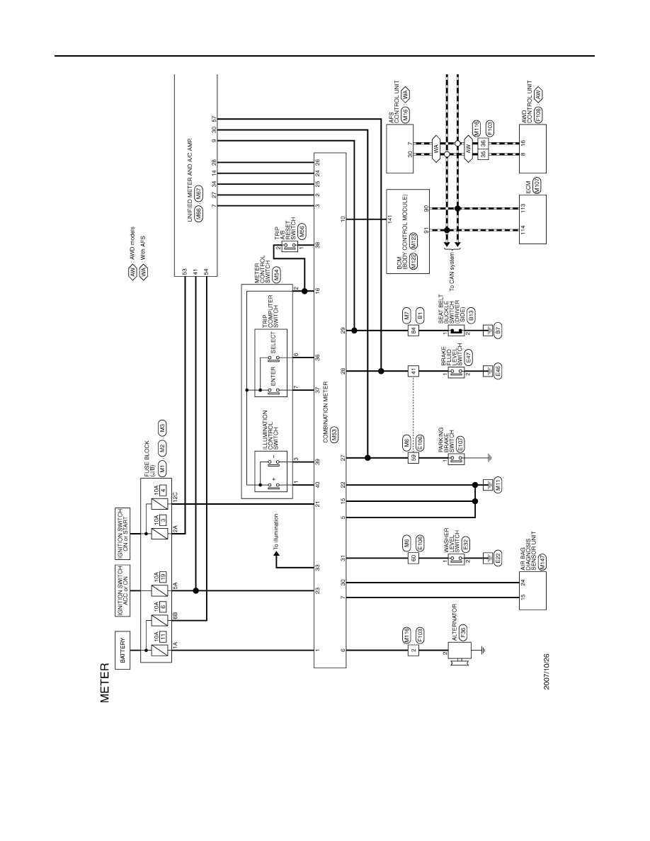
Wiring Diagram - METER -
INFOID:0000000003757122
JCNWM0708GB
Нет комментариевНе стесняйтесь поделиться с нами вашим ценным мнением.
Текст