Infiniti EX35. Manual — part 1470
TM-268
< DISASSEMBLY AND ASSEMBLY >
[5AT: RE5R05A]
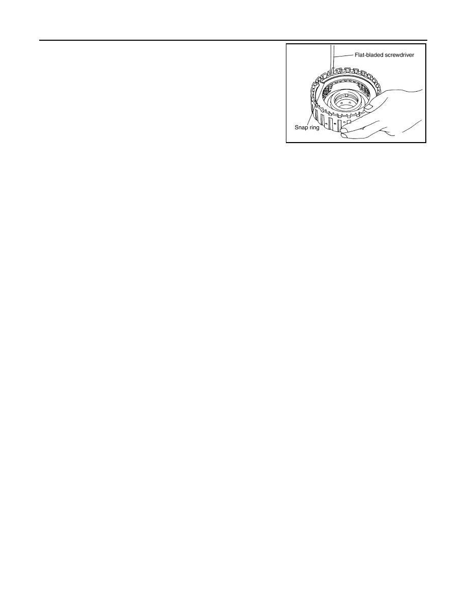
DIRECT CLUTCH
2.
Using a flat-bladed screwdriver, install snap ring in direct clutch
drum.
Inspection
INFOID:0000000003130673
Check the following, and replace direct clutch assembly if necessary.
• Direct Clutch Snap Ring
Check for deformation, fatigue or damage.
• Direct Clutch Drive Plates and Driven Plates
Check facing for burns, cracks or damage.
• Direct Clutch Dish Plate and Retaining Plates
Check facing for burns, cracks or damage.
SCIA2868E
SERVICE DATA AND SPECIFICATIONS (SDS)
TM-269
< SERVICE DATA AND SPECIFICATIONS (SDS)
[5AT: RE5R05A]
C
E
F
G
H
I
J
K
L
M
A
B
TM
N
O
P
SERVICE DATA AND SPECIFICATIONS (SDS)
SERVICE DATA AND SPECIFICATIONS (SDS)
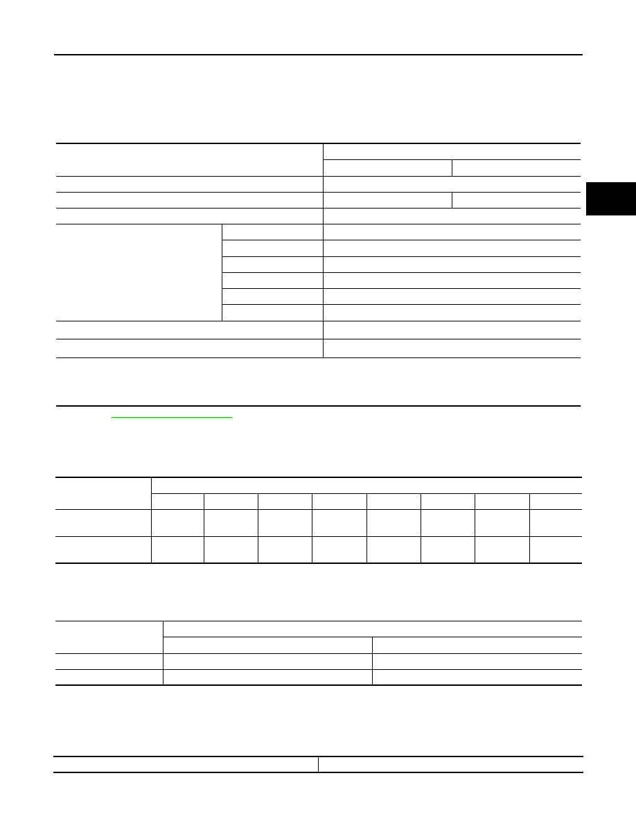
General Specification
INFOID:0000000003130674
• *1: Refer to
MA-10, "Fluids and Lubricants"
• *2: The fluid capacity is the reference value. Check the fluid level with A/T fluid level gauge.
Vehicle Speed at Which Gear Shifting Occurs
INFOID:0000000003130675
• At half throttle, the accelerator opening is 4/8 of the full opening.
Vehicle Speed at Which Lock-up Occurs/Releases
INFOID:0000000003130676
• At closed throttle, the accelerator opening is less than 1/8 condition. (Closed throttle position signal OFF)
• At half throttle, the accelerator opening is 4/8 of the full opening.
Stall Speed
INFOID:0000000003130677
Applied model
VQ35HR engine
2WD
AWD
Automatic transmission model
RE5R05A
Transmission model code number
98X6E
98X7A
Stall torque ratio
1.74 : 1
Transmission gear ratio
1st
3.842
2nd
2.353
3rd
1.529
4th
1.000
5th
0.839
Reverse
2.765
Recommended fluid
Genuine NISSAN Matic S ATF
*1
Fluid capacity
10.3 liter (10-7/8 US qt, 9-1/8 Imp qt)
*2
CAUTION:
• If Genuine NISSAN Matic S ATF is not available, Genuine NISSAN Matic J ATF may also be used.
• Using ATF other than Genuine NISSAN Matic S ATF or Matic J ATF will cause deterioration in driveability and A/T durability,
and may damage the A/T, which is not covered by the INFINITI new vehicle limited warranty.
Throttle position
Vehicle speed
km/h (MPH)
D
1
→
D
2
D
2
→
D
3
D
3
→
D
4
D
4
→
D
5
D
5
→
D
4
D
4
→
D
3
D
3
→
D
2
D
2
→
D
1
Full throttle
70 – 74
(44 – 46)
114 – 122
(71 – 76)
172 – 182
(107 – 113)
246 – 256
(153 – 159)
242 – 252
(150 – 157)
157 – 167
(98 – 104)
98 – 106
(61 – 66)
43 – 47
(27 – 29)
Half throttle
47 – 51
(29 – 32)
77 – 83
(48 – 52)
100 – 108
(62 – 67)
167 – 175
(104 – 109)
137 – 145
(85 – 90)
63 – 71
(39 – 44)
32 – 38
(20 – 24)
7 – 11
(4 – 7)
Throttle position
Vehicle speed
km/h (MPH)
Lock-up ON
Lock-up OFF
Closed throttle
57 – 65 (35 – 40)
54 – 62 (34 – 39)
Half throttle
167 – 175 (104 – 109)
137 – 145 (85 – 90)
Stall speed
2,700 – 3,000 rpm

TM-270
< SERVICE DATA AND SPECIFICATIONS (SDS)
[5AT: RE5R05A]
SERVICE DATA AND SPECIFICATIONS (SDS)
Line Pressure
INFOID:0000000003130678
Turbine Revolution Sensor
INFOID:0000000003130679
Vehicle Speed Sensor A/T (Revolution Sensor)
INFOID:0000000003130680
Reverse Brake
INFOID:0000000003130681
Total End Play
INFOID:0000000003130682
BEARING RACE FOR ADJUSTING TOTAL END PLAY
Torque Converter
INFOID:0000000003130683
Engine speed
Line pressure
kPa (kg/cm
2
, psi)
“R” position
“D” and “M” positions
At idle speed
425 – 465 (4.4 – 4.7, 62 – 67)
379 – 428 (3.9 – 4.3, 55 – 62)
At stall speed
1,605 – 1,950 (16.4 – 19.9, 233 – 282)
1,310 – 1,500 (13.4 – 15.3, 190 – 217)
Name
Condition
Data (Approx.)
Turbine revolution sensor 1
When running at 50 km/h (31 MPH) in 4th speed witch the closed throttle position
signal OFF.
1.3 kHz
Turbine revolution sensor 2
When running at 20 km/h (12 MPH) in 1st speed witch the closed throttle position
signal OFF.
Name
Condition
Data (Approx.)
Revolution sensor
When running at 20 km/h (12 MPH).
185 Hz
Model code number
98X6E, 98X7A
Number of drive plates
6
Number of driven plates
6
Clearance
mm (in)
Standard
0.7 – 1.1 (0.028 – 0.043)
Thickness of retaining plates
mm (in)
4.2 (0.165)
4.4 (0.173)
4.6 (0.181)
4.8 (0.189)
5.0 (0.197)
5.2 (0.205)
5.4 (0.213)
Total end play
mm (in)
0.25 – 0.55 (0.0098 – 0.0217)
Thickness
mm (in)
0.8 (0.031)
1.0 (0.039)
1.2 (0.047)
1.4 (0.055)
1.6 (0.063)
1.8 (0.071)
Distance between end of converter housing and torque
converter
mm (in)
25.0 (0.98) or more
VTL-1
VENTILATION, HEATER & AIR CONDITIONER
C
D
E
F
G
H
J
K
L
M
SECTION
VTL
A
B
VTL
N
O
P
CONTENTS
VENTILATION SYSTEM
FUNCTION DIAGNOSIS . . . . . . . ...
SWITCHES AND THEIR CONTROL FUNC-
TION . . . . . . . . . . . . . . . . .
WITHOUT LEFT AND RIGHT VENTILATION TEM-
PERATURE SEPARATELY CONTROL SYSTEM . ..
WITH LEFT AND RIGHT VENTILATION TEMPER-
ATURE SEPARATELY CONTROL SYSTEM . . .....
AIR DISTRIBUTION . . . . . . . . . . .
System Description . . . . . . . . . . . . ...
PRECAUTION . . . . . . . . . . . ...
PRECAUTIONS . . . . . . . . . . . . ...
Precaution Necessary for Steering Wheel Rota-
tion after Battery Disconnect . . . . . . . . .....
Precaution for Procedure without Cowl Top Cover
. ..
Precautions For Xenon Headlamp Service . . . ...
Working with HFC-134a (R-134a) . . . . . . .....
General Refrigerant Precaution . . . . . . . ....
Refrigerant Connection . . . . . . . . . . .....
Service Equipment . . . . . . . . . . . . ..
COMPRESSOR . . . . . . . . . . . . ..
General Precautions . . . . . . . . . . . ...
LEAK DETECTION DYE . . . . . . . . .
General Precautions . . . . . . . . . . . ...
PREPARATION . . . . . . . . . . ...
PREPARATION . . . . . . . . . . . . .
Special Service Tool . . . . . . . . . . . .
Commercial Service Tool . . . . . . . . . .
Sealant or/and Lubricant . . . . . . . . . . .
ON-VEHICLE MAINTENANCE . . . . .
IN-CABIN MICROFILTER . . . . . . . . .
Exploded View . . . . . . . . . . . . . . .
Removal and Installation . . . . . . . . . . .
Replacement . . . . . . . . . . . . . . ...
ON-VEHICLE REPAIR . . . . . . . . .
PRESET SWITCH . . . . . . . . . . . .
Exploded View . . . . . . . . . . . . . . .
Removal and Installation . . . . . . . . . . .
UNIFIED METER AND A/C AMP. . . . . . .
Exploded View . . . . . . . . . . . . . . .
Removal and Installation . . . . . . . . . . .
AMBIENT SENSOR . . . . . . . . . . ..
Exploded View . . . . . . . . . . . . . . .
Removal and Installation . . . . . . . . . . .
IN-VEHICLE SENSOR . . . . . . . . . ..
Exploded View . . . . . . . . . . . . . . .
Removal and Installation . . . . . . . . . . .
SUNLOAD SENSOR . . . . . . . . . . .
Exploded View . . . . . . . . . . . . . . .
Removal and Installation . . . . . . . . . . .
INTAKE SENSOR . . . . . . . . . . . .
Exploded View . . . . . . . . . . . . . . .
Removal and Installation . . . . . . . . . . .
BLOWER UNIT . . . . . . . . . . . . .
Exploded View . . . . . . . . . . . . . . .
Removal and Installation . . . . . . . . . . .
Нет комментариевНе стесняйтесь поделиться с нами вашим ценным мнением.
Текст