Infiniti EX35. Manual — part 876
SERVICE INFORMATION FOR ELECTRICAL INCIDENT
GI-43
< BASIC INSPECTION >
C
D
E
F
G
H
I
J
K
L
M
B
GI
N
O
P
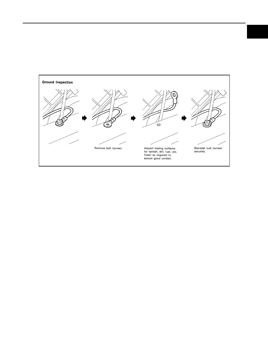
• When inspecting a ground connection follow these rules:
- Remove the ground bolt or screw.
- Inspect all mating surfaces for tarnish, dirt, rust, etc.
- Clean as required to assure good contact.
- Reinstall bolt or screw securely.
- Inspect for “add-on” accessories which may be interfering with the ground circuit.
- If several wires are crimped into one ground eyelet terminal, check for proper crimps. Make sure all of the
wires are clean, securely fastened and providing a good ground path. If multiple wires are cased in one eye-
let make sure no ground wires have excess wire insulation.
• For detailed ground distribution information, refer to “Ground Distribution” in PG section.
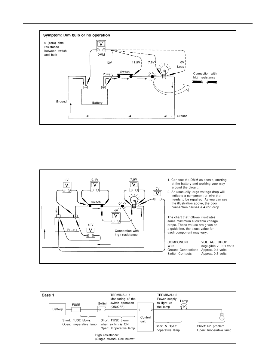
VOLTAGE DROP TESTS
• Voltage drop tests are often used to find components or circuits which have excessive resistance. A voltage
drop in a circuit is caused by a resistance when the circuit is in operation.
• Check the wire in the illustration. When measuring resistance with DMM, contact by a single strand of wire
will give reading of 0 ohms. This would indicate a good circuit. When the circuit operates, this single strand
of wire is not able to carry the current. The single strand will have a high resistance to the current. This will
be picked up as a slight voltage drop.
• Unwanted resistance can be caused by many situations as follows:
- Undersized wiring (single strand example)
- Corrosion on switch contacts
- Loose wire connections or splices.
• If repairs are needed always use wire that is of the same or larger gauge.
Measuring Voltage Drop — Accumulated Method
• Connect the DMM across the connector or part of the circuit you want to check. The positive lead of the
DMM should be closer to power and the negative lead closer to ground.
• Operate the circuit.
• The DMM will indicate how many volts are being used to “push” current through that part of the circuit.
SGI853
GI-44
< BASIC INSPECTION >
SERVICE INFORMATION FOR ELECTRICAL INCIDENT
Note in the illustration that there is an excessive 4.1 volt drop between the battery and the bulb.
Measuring Voltage Drop — Steb-by-Step
• The step-by-step method is most useful for isolating excessive drops in low voltage systems (such as those
in “Computer Controlled Systems”).
• Circuits in the “Computer Controlled System” operate on very low amperage.
• The (Computer Controlled) system operations can be adversely affected by any variation in resistance in the
system. Such resistance variation may be caused by poor connection, improper installation, improper wire
gauge or corrosion.
• The step by step voltage drop test can identify a component or wire with too much resistance.
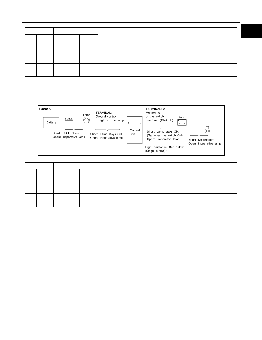
CONTROL UNIT CIRCUIT TEST
System Description
• When the switch is ON, the control unit lights up the lamp.
CASE 1
SGI974
SAIA0258E
MGI034A
SERVICE INFORMATION FOR ELECTRICAL INCIDENT
GI-45
< BASIC INSPECTION >
C
D
E
F
G
H
I
J
K
L
M
B
GI
N
O
P
INPUT-OUTPUT VOLTAGE CHART
• The voltage value is based on the body ground.
• *: If high resistance exists in the switch side circuit (caused by a single strand), terminal 1 does not detect battery voltage. Control unit
does not detect the switch is ON even if the switch does not turn ON. Therefore, the control unit does not supply power to light up the
lamp.
CASE 2
INPUT-OUTPUT VOLTAGE CHART
• The voltage value is based on the body ground.
• *: If high resistance exists in the switch side circuit (caused by a single strand), terminal 2 does not detect approx. 0V. Control unit
does not detect the switch is ON even if the switch does not turn ON. Therefore, the control unit does not control ground to light up the
lamp.
Terminal No.
Description
Condition
Value (Approx.)
In case of high resistance such as single
strand (V) *
+
−
Signal name
Input/
Output
1
Body
ground
Switch
Input
Switch ON
Battery voltage
Lower than battery voltage Approx. 8 (Ex-
ample)
Switch OFF
0 V
Approx. 0
2
Body
ground
Lamp
Output
Switch ON
Battery voltage
Approx. 0 (Inoperative lamp)
Switch OFF
0 V
Approx. 0
Terminal No.
Description
Condition
Value (Approx.)
In case of high resistance such as single
strand (V) *
+
−
Signal name
Input/
Output
1
Body
ground
Lamp
Output
Switch ON
0V
Battery voltage (Inoperative lamp)
Switch OFF
Battery voltage
Battery voltage
2
Body
ground
Switch
Input
Switch ON
0 V
Higher than 0 Approx. 4 (Example)
Switch OFF
5 V
Approx. 5
MGI035A
GI-46
< BASIC INSPECTION >
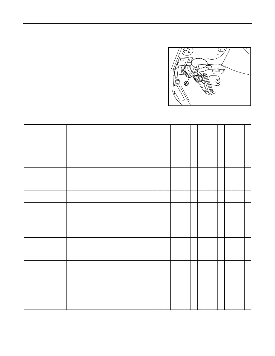
CONSULT-III/GST CHECKING SYSTEM
CONSULT-III/GST CHECKING SYSTEM
Description
INFOID:0000000003131640
• When CONSULT-III/GST is connected with a data link connector
(A) equipped on the vehicle side, it will communicate with the con-
trol unit equipped in the vehicle and then enable various kinds of
diagnostic tests.
• Refer to “CONSULT-III Software Operation Manual” for more infor-
mation.
CONSULT-III Function and System Application*1
INFOID:0000000003566328
x: Applicable
*1: If GST application is equipped, functions in accordance with SAE J1979 and ISO 15031-5 can be used.
CONSULT-III/GST Data Link Connector (DLC) Circuit
INFOID:0000000003131642
INSPECTION PROCEDURE
1
: Instrument driver lower panel
JPAIA0243ZZ
Diagnostic test mode
Function
ENGINE
T
R
ANSMI
SSION
AI
R BAG
METER/
M&A
BCM
AUT
O
DRIVE
POS.
ABS (I
ncluding
VDC
)
IPDM
E/R
ALL MO
DE
A
W
D/4WD
MUL
TI
A
V
ICC
LANE
CAM
SONAR
ADA
P
TI
VE LIGHT
Work Support
This mode enables a technician to adjust some de-
vices faster and more accurately.
x
x
-
-
x
x
x
-
-
-
x
x
x
x
Self-Diagnostic Re-
sults
Retrieve DTC from ECU and display diagnostic
items.
x
x
x
x
x
x
x
x
x
x
x
x
x
x
Data Monitor
Monitor the input/output signal of the control unit in
real time.
x
x
-
x
x
x
x
x
x
x
x
x
x
x
CAN Diagnosis
This mode displays a network diagnosis result about
CAN by a diagram.
x
x
-
x
x
x
x
x
x
x
x
x
-
x
CAN Diagnosis Sup-
port Monitor
It monitors the status of CAN communication.
x
x
-
x
x
x
x
x
x
x
x
x
-
x
Active Test
Send the drive signal from CONSULT-III to the actu-
ator. The operation check can be performed.
x
-
-
-
x
x
x
x
x
-
x
x
x
x
DTC & SRT confirma-
tion
The status of system monitoring tests and the self-
diagnosis status/result can be confirmed.
x
x
-
-
-
-
-
-
-
-
-
-
-
-
ECU Identification
Display the ECU identification number (part number
etc.) of the selected system.
x
x
-
-
x
x
x
x
x
x
x
x
x
x
Function Test
This mode can show results of self-diagnosis of ECU
with either "OK" or "NG". For engine, more practical
tests regarding sensors/switches and/or actuators
are available.
x
-
x
-
-
-
x
-
-
-
-
-
-
-
Configuration
When ECU is replaced with a new one, etc., write
the information and set the ECU to perform the con-
trol that is applicable to the vehicle.
-
-
-
-
x
-
-
-
-
-
-
-
-
-
Special Function
Other results or histories, etc. that are recorded in
ECU are displayed.
-
-
-
-
-
-
-
-
-
-
-
-
-
-
Нет комментариевНе стесняйтесь поделиться с нами вашим ценным мнением.
Текст