Infiniti EX35. Manual — part 727

CYLINDER HEAD
EM-107
< DISASSEMBLY AND ASSEMBLY >
C
D
E
F
G
H
I
J
K
L
M
A
EM
N
P
O
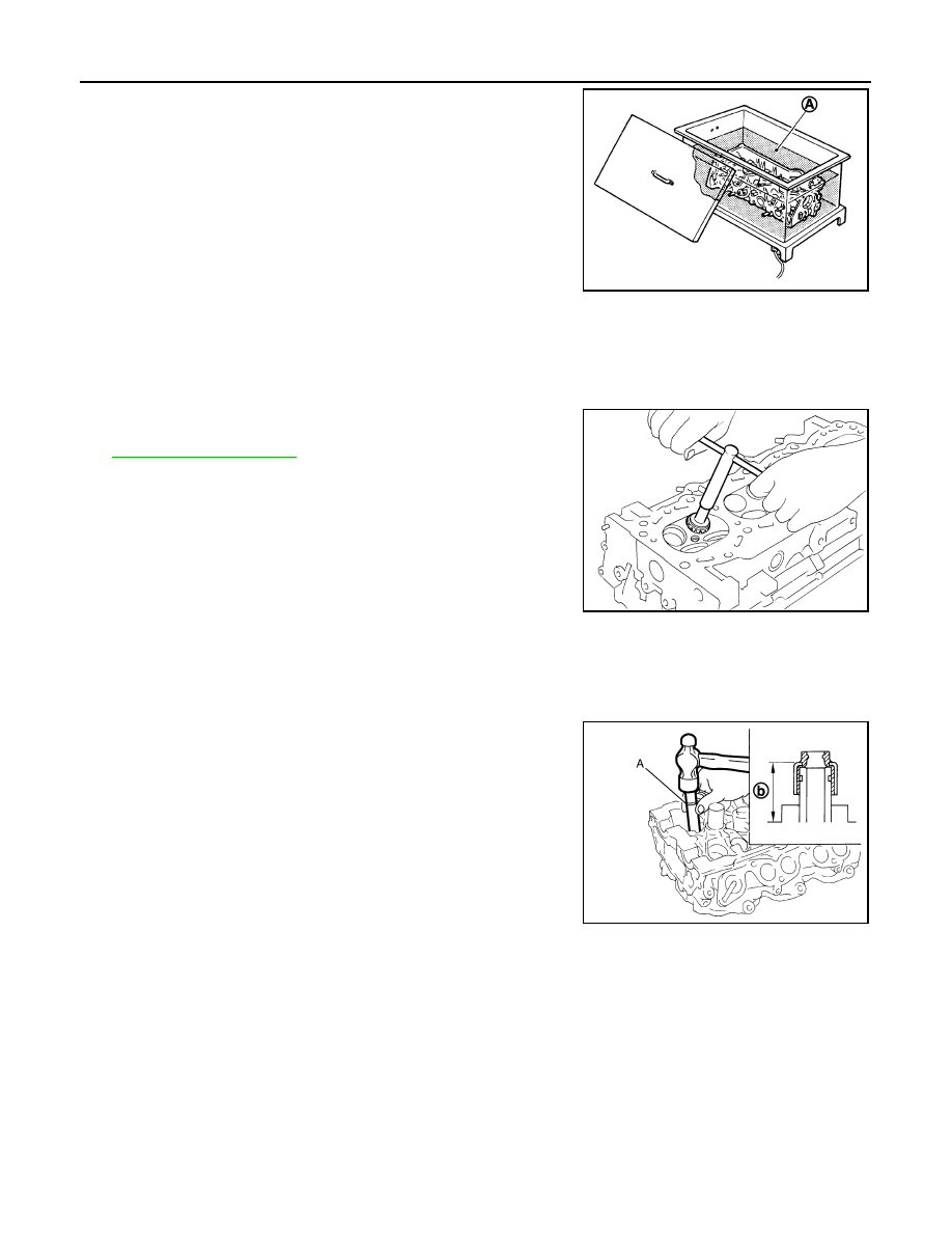
b.
Heat cylinder head to 110 to 130
°
C (230 to 266
°
F) by soaking in
heated oil (A).
c.
Using the valve guide drift (commercial service tool), press valve
guide from camshaft side to the dimensions as shown in the fig-
ure.
WARNING:
Cylinder head contains heat. When working, wear protec-
tive equipment to avoid getting burned.
d.
Using the valve guide reamer (commercial service tool) (A),
apply reamer finish to valve guide.
2.
If valve seat is removed in step 9 (DISASSEMBLY), install it.
Replace with oversize [0.5 mm (0.020 in)] valve seat.
a.
Ream cylinder head recess diameter (a) for service valve seat.
• Be sure to ream in circles concentric to valve guide center.
This will enable valve to fit correctly.
JPBIA0184ZZ
Projection (A)
Intake and exhaust
: Refer to
JPBIA0186ZZ
Standard
: Refer to
.
(Intake and exhaust)
JPBIA0185ZZ
Oversize
: Refer to
.
(Intake and exhaust)
JPBIA0188ZZ
EM-108
< DISASSEMBLY AND ASSEMBLY >
CYLINDER HEAD
b.
Heat cylinder head to 110 to 130
°
C (230 to 266
°
F) by soaking in
heated oil (A).
c.
Provide valve seats cooled well with dry ice. Force fit valve seat into cylinder head.
WARNING:
Cylinder head contains heat. When working, wear protective equipment to avoid getting burned.
CAUTION:
Never directly touching cold valve seats.
d.
Using the valve seat cutter set (commercial service tool) or valve
seat grinder, finish seat to the specified dimensions. Refer to
CAUTION:
When using the valve seat cutter, firmly grip cutter handle
with both hands. Then, press on the contacting surface all
around the circumference to cut in a single drive. Improper
pressure on with cutter or cutting many different times may
result in stage valve seat.
e.
Using compound, grind to adjust valve fitting.
f.
Check again for normal contact. Refer to "VALVE SEAT CONTACT".
3.
Install new valve oil seals as follows:
a.
Apply new engine oil on valve oil seal joint and seal lip.
b.
Install with the valve oil seal drift [SST: KV10115600 (J-38958)]
(A) to match dimension in the figure.
4.
Install valve spring seat.
5.
Install valve.
NOTE:
Larger diameter valves are for intake side.
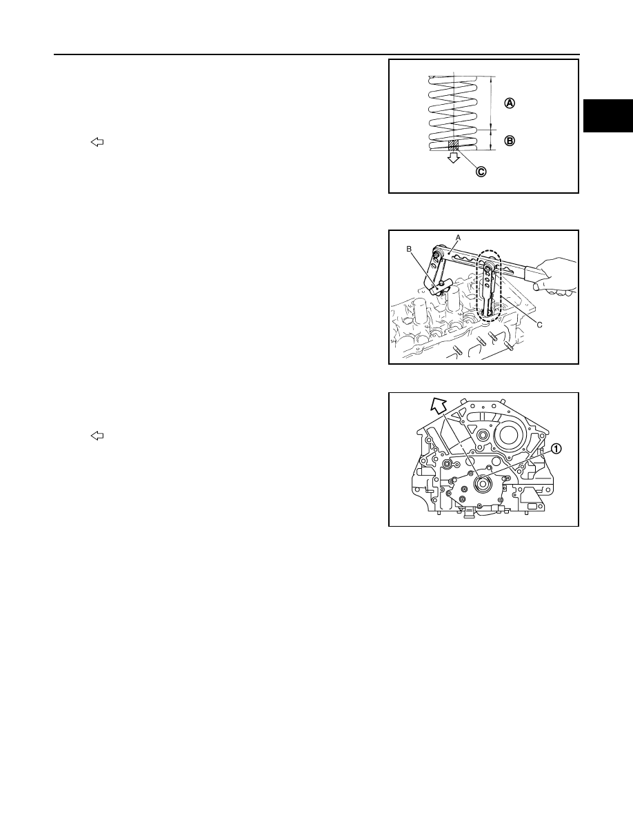
6.
Install valve spring (uneven pitch type).
JPBIA0184ZZ
SEM934C
Height (b) (Without valve spring seat installed)
Intake and exhaust
: 14.3 - 14.9 mm (0.563 - 0.587 in)
JPBIA0178ZZ
CYLINDER HEAD
EM-109
< DISASSEMBLY AND ASSEMBLY >
C
D
E
F
G
H
I
J
K
L
M
A
EM
N
P
O
• Install narrow pitch end to cylinder head side (valve spring
seat side).
7.
Install valve spring retainer.
8.
Install valve collet.
• Compress valve spring with the valve spring compressor [SST:
KV10116200 (J26336-A)] (A), the attachment [SST:
KV10115900 (J26336-20)] (C) and the adapter [SST:
KV10116200 (
—
)] (B). Install valve collet with a magnet
hand.
CAUTION:
When working, take care not to damage valve lifter holes.
• Tap valve stem edge lightly with plastic hammer after installa-
tion to check its installed condition.
9.
Install new cylinder head gaskets.
10. Turn crankshaft until No. 1 piston is set at TDC.
• Crankshaft key should line up with the bank 1 cylinder center
line as shown in the figure.
A
: Wide pitch
B
: Narrow pitch
C
: Paint mark
: Cylinder head side
Paint mark color
: Yellowish green
JPBIA0179ZZ
JPBIA0180ZZ
1
: Crankshaft key
: Bank 1 side
JPBIA0174ZZ

EM-110
< DISASSEMBLY AND ASSEMBLY >
CYLINDER HEAD
11. Install cylinder head follow the steps below to tighten cylinder
head bolts in numerical order as shown in the figure with cylin-
der head bolts wrench (commercial service tool).
CAUTION:
• If cylinder head bolts re-used, check their outer diameters
before installation. Refer to
.
• Before installing cylinder head, inspect cylinder head dis-
tortion. Refer to
.
a.
Apply new engine oil to threads and seat surfaces of cylinder
head bolts.
b.
Tighten all cylinder head bolts.
c.
Completely loosen all cylinder head bolts.
CAUTION:
In step “c”, loosen bolts in reverse order of that indicated in the figure.
d.
Tighten all cylinder head bolts.
e.
Turn all cylinder head bolts 95 degrees clockwise (angle tightening).
CAUTION:
Check the tightening angle by using the angle wrench [SST:
KV10112100 (BT8653-A)] (A). Never make judgment by
visual inspection.
• Check tightening angle indicated on the angle wrench indica-
tor plate.
f.
Turn all cylinder head bolts 95 degrees clockwise again (angle
tightening).
12. After installing cylinder head, measure distance between front
end faces of cylinder block and cylinder head (bank 1 and bank
2).
• If measured value is out of the standard, reinstall cylinder
head.
13. Install valve lifter.
• Install it in the original position.
14. Install spark plug tube.
• Press-fit spark plug tube as follows:
A
: Bank 1
B
: Bank 2
: Engine front
: 105 N·m (11 kg-m, 77 ft-lb)
: 0 N·m (0 kg-m, 0 ft-lb)
: 40.0 N·m (4.1 kg-m, 30 ft-lb)
JPBIA0172ZZ
JPBIA0175ZZ
Standard
: 14.1 - 14.9 mm (0.555 - 0.587 in)
EMQ0662D
Нет комментариевНе стесняйтесь поделиться с нами вашим ценным мнением.
Текст