Infiniti EX35. Manual — part 772
EXL-132
< ECU DIAGNOSIS >
[XENON TYPE]
BCM (BODY CONTROL MODULE)
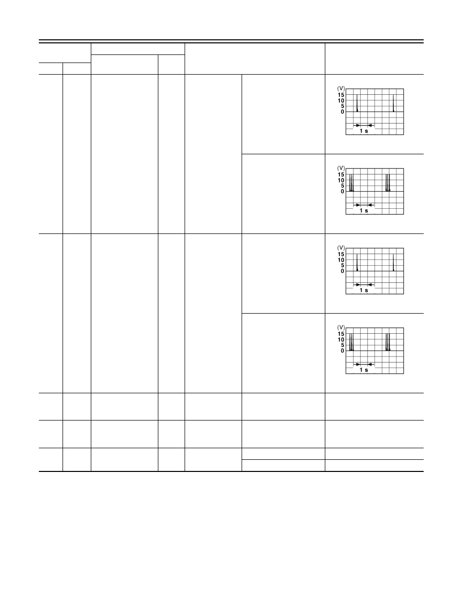
78
(Y)
Ground
Room antenna (
−
)
(Instrument panel)
Output
Ignition switch
OFF
When Intelligent Key is in
the passenger compart-
ment
When Intelligent Key is not
in the passenger compart-
ment
79
(BR)
Ground
Room antenna (+)
(Instrument panel)
Output
Ignition switch
OFF
When Intelligent Key is in
the passenger compart-
ment
When Intelligent Key is not
in the passenger compart-
ment
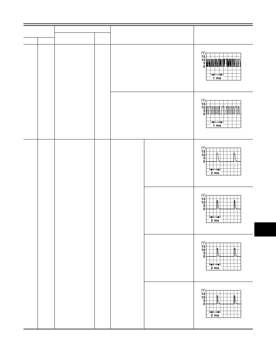
80
(GR)
Ground
NATS antenna amp
(Built in key slot)
Input/
Output
During waiting
Ignition switch is pressed
while inserting the key into
the key slot.
Just after pressing ignition
switch. Pointer of tester should
move.
81
(W)
Ground
NATS antenna amp
(Built in key slot)
Input/
Output
During waiting
Ignition switch is pressed
while inserting the key into
the key slot.
Just after pressing ignition
switch. Pointer of tester should
move.
82
(R)
Ground
Ignition relay [Fuse
block (J/B)] control
Output
Ignition switch
OFF or ACC
0 V
ON
Battery voltage
Terminal No.
(Wire color)
Description
Condition
Value
(Approx.)
Signal name
Input/
Output
+
–
JMKIA0062GB
JMKIA0063GB
JMKIA0062GB
JMKIA0063GB
BCM (BODY CONTROL MODULE)
EXL-133
< ECU DIAGNOSIS >
[XENON TYPE]
C
D
E
F
G
H
I
J
K
M
A
B
EXL
N
O
P
83
(Y)
Ground
Remote keyless entry
receiver signal
Input/
Output
During waiting
When operating either button on the key
87
(BR)
Ground
Combination switch
INPUT 5
Input
Combination
switch
All switch OFF
(Wiper intermittent dial 4)
1.4 V
Front fog lamp switch ON
(Wiper intermittent dial 4)
1.3 V
Rear wiper switch ON
(Wiper intermittent dial 4)
1.3 V
Any of the conditions below
with all switch OFF
• Wiper intermittent dial 1
• Wiper intermittent dial 2
• Wiper intermittent dial 6
• Wiper intermittent dial 7
1.3 V
Terminal No.
(Wire color)
Description
Condition
Value
(Approx.)
Signal name
Input/
Output
+
–
JMKIA0064GB
JMKIA0065GB
JPMIA0041GB
JPMIA0037GB
JPMIA0039GB
JPMIA0040GB

EXL-134
< ECU DIAGNOSIS >
[XENON TYPE]
BCM (BODY CONTROL MODULE)
88
(V)
Ground
Combination switch
INPUT 3
Input
Combination
switch
All switch OFF
(Wiper intermittent dial 4)
1.4 V
Lighting switch HI
(Wiper intermittent dial 4)
1.3 V
Lighting switch 2ND
(Wiper intermittent dial 4)
1.3 V
Rear washer switch ON
(Wiper intermittent dial 4)
1.3 V
Any of the conditions below
with all switch OFF
• Wiper intermittent dial 1
• Wiper intermittent dial 2
• Wiper intermittent dial 3
1.3 V
89
(BR)
Ground
Push-button ignition
switch (Push switch)
Input
Push-button igni-
tion switch (push
switch)
Pressed
0 V
Not pressed
Battery voltage
90
(P)
Ground
CAN-L
Input/
Output
—
—
91
(L)
Ground
CAN-H
Input/
Output
—
—
Terminal No.
(Wire color)
Description
Condition
Value
(Approx.)
Signal name
Input/
Output
+
–
JPMIA0041GB
JPMIA0036GB
JPMIA0037GB
JPMIA0039GB
JPMIA0040GB
BCM (BODY CONTROL MODULE)
EXL-135
< ECU DIAGNOSIS >
[XENON TYPE]
C
D
E
F
G
H
I
J
K
M
A
B
EXL
N
O
P
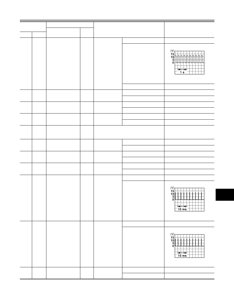
92
(LG)
Ground
Key slot illumination
Output
Key slot illumina-
tion
OFF
Battery voltage
Blinking
6.5 V
ON
0 V
93
(V)
Ground
ON indicator lamp
Output
Ignition switch
OFF or ACC
Battery voltage
ON
0 V
94
(Y)
Ground
Puddle lamp control
Output
Puddle lamp
OFF
Battery voltage
ON
0 V
95
(O)
Ground
ACC relay control
Output
Ignition switch
OFF
0 V
ACC or ON
Battery voltage
96
(GR)
Ground
Control device (De-
tention switch) power
supply
Output
—
Battery voltage
97
(L)
Ground
Steering lock condi-
tion No. 1
Input
Steering lock
LOCK status
0 V
UNLOCK status
Battery voltage
98
(P)
Ground
Steering lock condi-
tion No. 2
Input
Steering lock
LOCK status
Battery voltage
UNLOCK status
0 V
99
(R)
Ground
Selector lever P posi-
tion switch
Input
Selector lever
P position
0 V
Any position other than P
Battery voltage
100
(G)
Ground
Passenger door re-
quest switch
Input
Passenger door
request switch
ON (Pressed)
0 V
OFF (Not pressed)
1.0 V
101
(SB)
Ground
Driver door request
switch
Input
Driver door re-
quest switch
ON (Pressed)
0 V
OFF (Not pressed)
1.0 V
102
(O)
Ground
Blower fan motor re-
lay control
Output
Ignition switch
OFF or ACC
0 V
ON
Battery voltage
Terminal No.
(Wire color)
Description
Condition
Value
(Approx.)
Signal name
Input/
Output
+
–
JPMIA0015GB
JPMIA0016GB
JPMIA0016GB
Нет комментариевНе стесняйтесь поделиться с нами вашим ценным мнением.
Текст