Infiniti EX35. Manual — part 757
EXL-72
< COMPONENT DIAGNOSIS >
[XENON TYPE]
XENON HEADLAMP
YES
>> Replace HID control unit.
NO
>> GO TO 3.
3.
CHECK XENON HEADLAMP HOUSING ASSEMBLY
Install the normal xenon headlamp housing assembly to the applicable headlamp. Check that the xenon head-
lamp is turned ON.
Is the headlamp turned ON?
YES
>> Replace the front combination lamp. (Xenon headlamp housing voltage converter malfunctions.)
NO
>> Xenon headlamp is normal. check the headlamp control system.
HEADLAMP LEVELIZER CIRCUIT
EXL-73
< COMPONENT DIAGNOSIS >
[XENON TYPE]
C
D
E
F
G
H
I
J
K
M
A
B
EXL
N
O
P
HEADLAMP LEVELIZER CIRCUIT
Description
INFOID:0000000003135337
The headlamp levelizer adjusts the headlamp light axis upward and downward with the aiming motor inte-
grated in the front combination lamp.
Component Function Check
INFOID:0000000003135338
1.
CHECK AIMING MOTOR OPERATION
CONSULT-III ACTIVE TEST
1.
Start the engine.
2.
Turn the lighting switch 2ND.
3.
Select “LEVELIZER TEST” of ADAPTIVE LIGHT active test item.
4.
With operating the test item, check the operation.
Is the operation normal?
YES
>> Headlamp levelizer circuit is normal.
NO
>> Refer to
.
Diagnosis Procedure
INFOID:0000000003135339
1.
CHECK AIMING MOTOR DRIVE SIGNAL OUTPUT
CONSULT-III ACTIVE TEST
1.
Start the engine.
2.
Turn the light switch 2ND.
3.
Select “LEVELIZER TEST” of ADAPTIVE LIGHT active test item.
4.
With operating the test item, check the voltage between the AFS control unit harness connector and the
ground.
Is the measurement value normal?
YES
>> GO TO 2.
NO
>> GO TO 3.
2.
CHECK AIMING MOTOR DRIVE SIGNAL CIRCUIT INPUT
1.
Turn the ignition switch OFF.
2.
Disconnect AFS control unit connector and aiming motor connector.
3.
Check continuity between AFS control unit harness connector and the aiming motor harness connector.
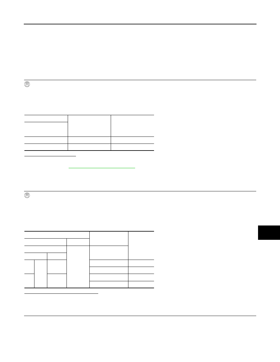
Test item
Light axis angle
(Reference value)
10 m (32.8 ft)-forward
light axis change refer-
ence quantity
(Approx.)
LEVELIZER TEST
Origin
0
°
—
Peak
2.5
°
450 mm (17.9 in)
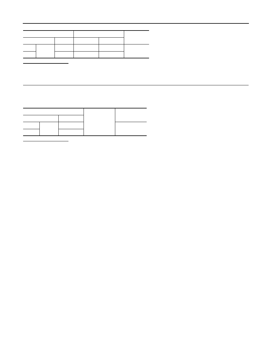
Terminals
Test item
Voltage
(Approx.)
(+)
(
−
)
AFS control unit
Ground
LEVELIZER TEST
Connector
Terminal
RH
M16
19
Origin
8.8 V
Peak
1.9 V
LH
40
Origin
8.8 V
Peak
1.9 V
EXL-74
< COMPONENT DIAGNOSIS >
[XENON TYPE]
HEADLAMP LEVELIZER CIRCUIT
Does continuity exist?
YES
>> Replace the front combination lamp.
NO
>> Repair the harnesses and connectors.
3.
CHECK AIMING MOTOR DRIVE SIGNAL SHORT CIRCUIT
1.
Turn the ignition switch OFF.
2.
Disconnect AFS control unit connector and aiming motor connector.
3.
Check continuity between AFS control unit harness connector and ground.
Does continuity exist?
YES
>> Repair the harness and connectors.
NO
>> Replace AFS control unit.
AFS control unit
Aiming motor
Continuity
Connector
Terminal
Connector
Terminal
RH
M16
19
E26
1
Existed
LH
40
E56
1
AFS control unit
Ground
Continuity
Connector
Terminal
RH
M16
19
Not existed
LH
40
FRONT FOG LAMP CIRCUIT
EXL-75
< COMPONENT DIAGNOSIS >
[XENON TYPE]
C
D
E
F
G
H
I
J
K
M
A
B
EXL
N
O
P
FRONT FOG LAMP CIRCUIT
Component Function Check
INFOID:0000000003135340
1.
CHECK FRONT FOG LAMP OPERATION
IPDM E/R AUTO ACTIVE TEST
1.
Activate IPDM E/R auto active test. Refer to
PCS-11, "Diagnosis Description"
.
2.
Check that the front fog lamp is turned ON.
CONSULT-III ACTIVE TEST
1.
Select "EXTERNAL LAMPS" of IPDM E/R active test item.
2.
With operating the test items, Check that the front fog lamp is turned ON.
Is the front fog lamp turned ON?
YES
>> Front fog lamp circuit is normal.
NO
>> Refer to
.
Diagnosis Procedure
INFOID:0000000003135341
1.
CHECK FRONT FOG LAMP FUSE
1.
Turn the ignition switch OFF.
2.
Check that the following fuses are not fusing.
Is the fuse fusing?
YES
>> GO TO 2.
NO
>> GO TO 3.
2.
CHECK FRONT FOG LAMP SHORT CIRCUIT
1.
Disconnect IPDM E/R connector and the front fog lamp connector.
2.
Check continuity between the IPDM E/R harness connector and the ground.
Does continuity exist?
YES
>> Repair the harnesses or connectors. And then replace the fuse.
NO
>> Replace the fuse. (Replace IPDM E/R if the fuse is fusing again.)
3.
CHECK FRONT FOG LAMP BULB
Check the applicable lamp bulb.
Is the bulb normal?
YES
>> GO TO 4.
NO
>> Replace the bulb.
4.
CHECK FRONT FOG LAMP OUTPUT VOLTAGE
CONSULT-III ACTIVE TEST
1.
Disconnect the front fog lamp connector.
2.
Turn the ignition switch ON.
3.
Select "EXTERNAL LAMPS" of IPDM E/R active test item.
Fog
: Front fog lamp ON
Off
: Front fog lamp OFF
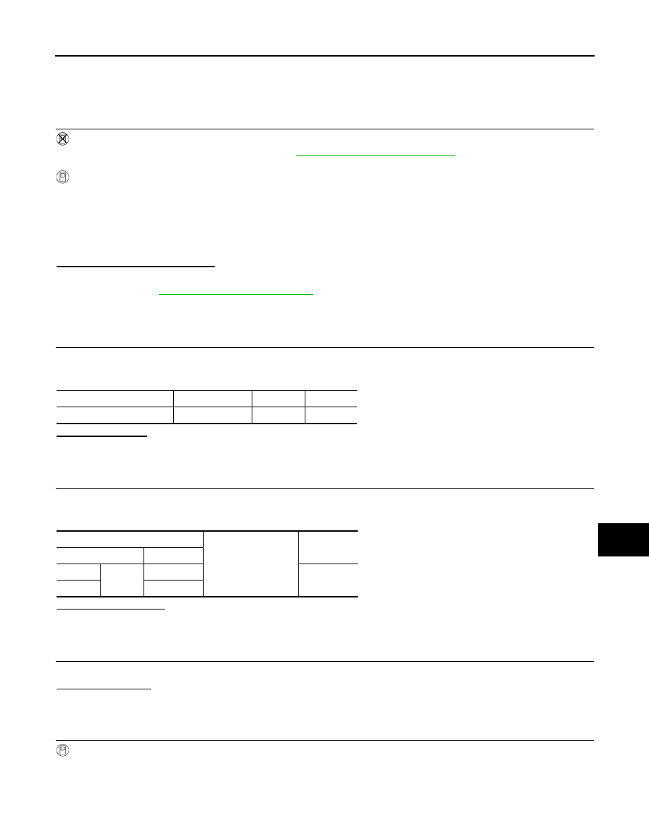
Unit
Location
Fuse No.
Capacity
Front fog lamp
IPDM E/R
#58
15 A
IPDM E/R
Ground
Continuity
Connector
Terminal
RH
E8
86
Not existed
LH
87
Нет комментариевНе стесняйтесь поделиться с нами вашим ценным мнением.
Текст