Infiniti EX35. Manual — part 317
BR-30
< ON-VEHICLE REPAIR >
BRAKE BOOSTER
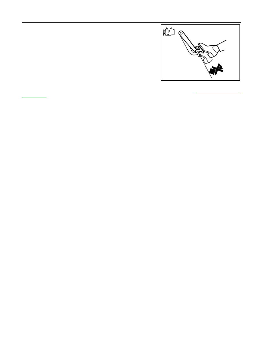
• Depress the brake pedal with the engine running. Then stop the
engine while holding down the brake pedal. Check that the brake
pedal stroke does not change after holding down the brake pedal
for 30 seconds or more.
NOTE:
A slight impact with a small click may be felt on the pedal when the
brake pedal is fully depressed. This is a normal phenomenon due
to the brake system operation.
ADJUSTMENT AFTER INSTALLATION
Perform the brake pedal adjustment after installing the brake pedal assembly. Refer to
.
JPFIA0044ZZ
VACUUM LINES
BR-31
< ON-VEHICLE REPAIR >
C
D
E
G
H
I
J
K
L
M
A
B
BR
N
O
P
VACUUM LINES
Exploded View
INFOID:0000000003140004
Removal and Installation
INFOID:0000000003140005
REMOVAL
1.
Remove the engine cover. Refer to
2.
Remove the cowl top cover. Refer to
.
3.
Remove the vacuum hose and tube.
INSTALLATION
Note the following, install in the reverse order of removal.
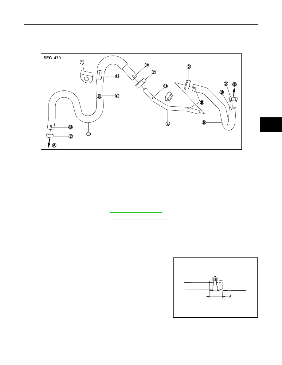
• Because vacuum hose contains a check valve, it must be installed in the correct position. Refer to the stamp
to confirm correct installation. Brake booster will not operate normally if the hose is installed in the wrong
direction.
• When installing vacuum hose, insert it until its tip reaches the
back-end of length (A) or further as shown in the figure.
- Face the marking side up when assembling.
CAUTION:
Never use lubricating oil during assembly.
Inspection
INFOID:0000000003140006
INSPECTION AFTER REMOVAL
Appearance
1.
Grommet
2.
Clamp
3.
Vacuum hose (built in check valve)
4.
Vacuum piping
5.
Vacuum hose
A.
To intake manifold
B.
Paint mark
C.
Stamp indicating engine direction
D.
Stamp indicating grommet installa-
tion position
E.
To brake booster
JPFIA0022ZZ
Standard
A
: 24 mm (0.95 in) or more
JPFIA0023ZZ
BR-32
< ON-VEHICLE REPAIR >
VACUUM LINES
Check for correct assembly, damage and deterioration.
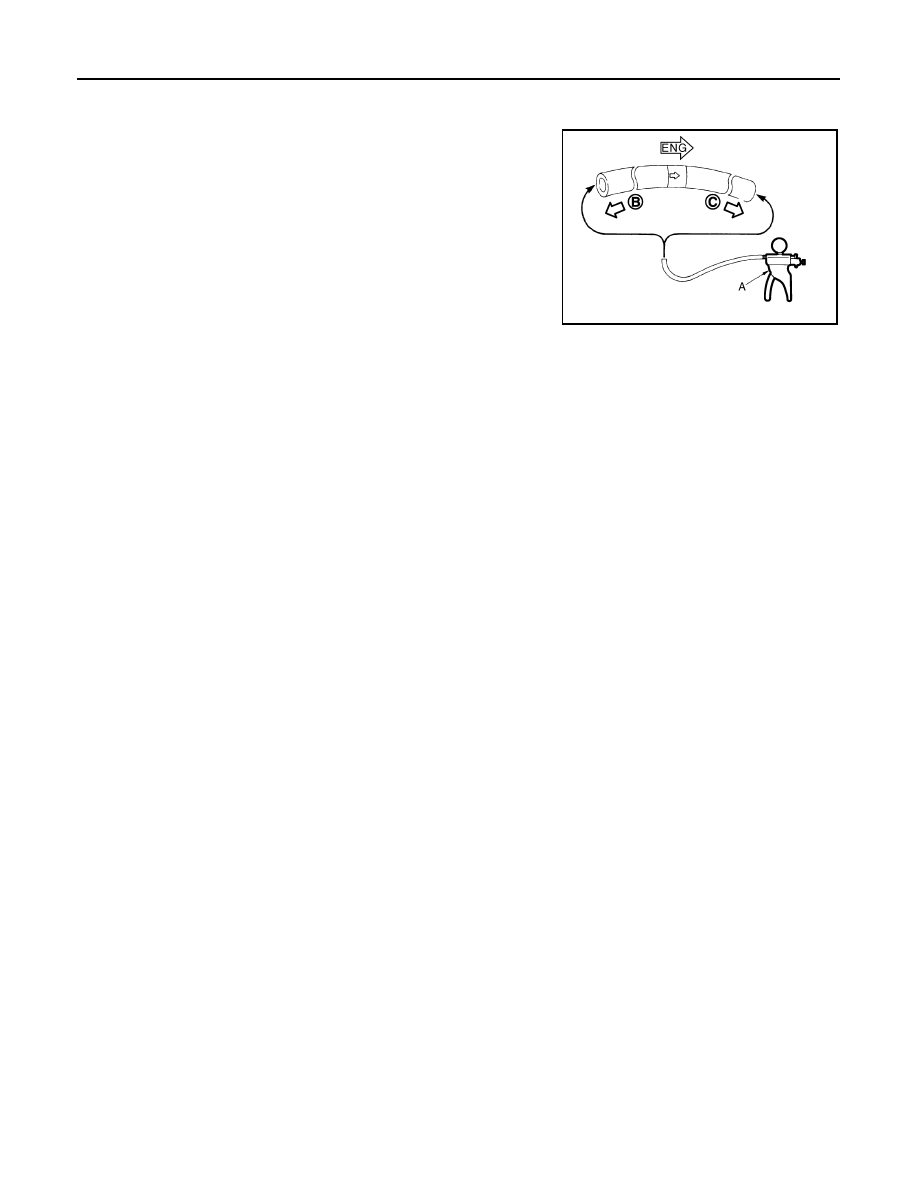
Check Valve Airtightness
• Use a handy vacuum pump (A) to check.
• Replace vacuum hose assembly if vacuum hose and check valve
are malfunctioning.
When connected to the booster side (B):
Vacuum should decrease within 1.3 kPa (9.8 mm-
Hg, 0.38 inHg) for 15 seconds under a vacuum of
−
66.7 kPa (
−
500 mmHg,
−
19.69 inHg).
When connected to the engine side (C):
Vacuum should not exist.
JPFIA0024ZZ
FRONT DISC BRAKE
BR-33
< ON-VEHICLE REPAIR >
C
D
E
G
H
I
J
K
L
M
A
B
BR
N
O
P
FRONT DISC BRAKE
BRAKE PAD
BRAKE PAD : Exploded View
INFOID:0000000003140010
BRAKE PAD : Removal and Installation
INFOID:0000000003140011
REMOVAL
WARNING:
Clean any dust from the brake caliper and brake pads with a vacuum dust collector. Never blow with
compressed air.
CAUTION:
• Never depress the brake pedal while removing the brake pads because the piston may pop out.
• Never spill or splash brake fluid on the disc rotor.
1.
Remove tires with power tool.
2.
Remove lower sliding pin bolt.
3.
Suspend the cylinder body with suitable wire so that the brake hose will not stretch. Then remove the
brake pads, shims, shim covers and pad retainers from the torque member.
CAUTION:
• Never deform the pad retainer when removing the pad retainer from the torque member.
• Never damage the piston boot.
• Never drop the brake pads, shims, and the shim covers.
INSTALLATION
WARNING:
Clean any dust from the brake caliper and brake pads with a vacuum dust collector. Never blow with
compressed air.
CAUTION:
• Never depress the brake pedal while removing the brake pads or the cylinder body because the pis-
ton may pop out.
• Never spill or splash brake fluid on the disc rotor.
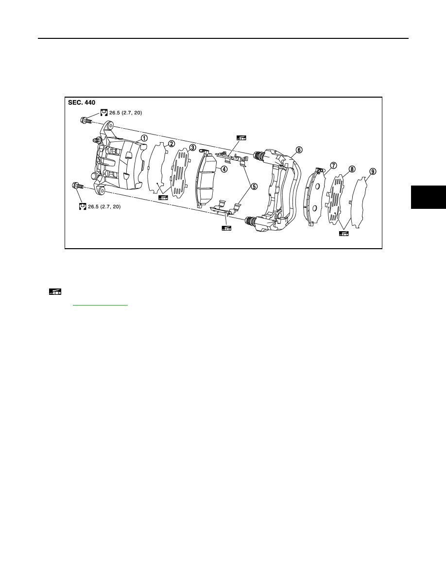
1.
Cylinder body
2.
Inner shim cover
3.
Inner shim
4.
Inner pad (with pad wear sensor)
5.
Pad retainer
6.
Torque member
7.
Outer pad (with pad wear sensor)
8.
Outer shim
9.
Outer shim cover
: Apply copper based brake grease.
Refer to
for symbols not described on the above.
JPFIA0327GB
Нет комментариевНе стесняйтесь поделиться с нами вашим ценным мнением.
Текст