Infiniti EX35. Manual — part 995
LAN
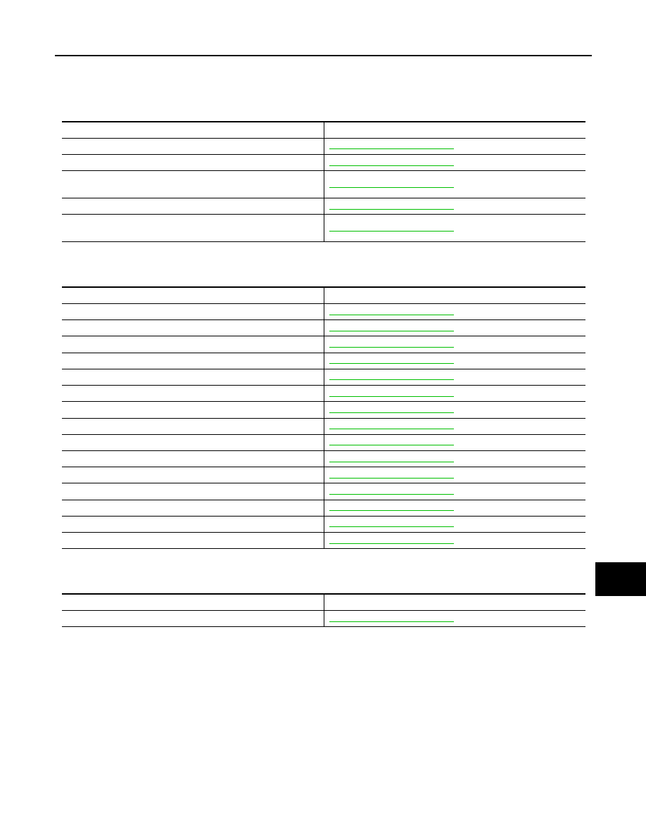
MALFUNCTION AREA CHART
LAN-39
< COMPONENT DIAGNOSIS >
[CAN]
C
D
E
F
G
H
I
J
K
L
B
A
O
P
N
MALFUNCTION AREA CHART
Main Line
INFOID:0000000003137635
Branch Line
INFOID:0000000003137636
Short Circuit
INFOID:0000000003137637
Malfunction Area
Reference
Main line between AV control unit and data link connector
Main line between data link connector and TCM
Main line between TCM and ABS actuator and electric unit (con-
trol unit)
Main line between TCM and driver seat control unit
Main line between driver seat control unit and ABS actuator and
electric unit (control unit)
Malfunction Area
Reference
ECM branch line circuit
Air bag diagnosis sensor unit branch line circuit
AFS control unit branch line circuit
AV control unit branch line circuit
Lane camera unit branch line circuit
AWD control unit branch line circuit
BCM branch line circuit
Data link connector branch line circuit
Unified meter and A/C amp. branch line circuit
Steering angle sensor branch line circuit
TCM branch line circuit
Driver seat control unit branch line circuit
ABS actuator and electric unit (control unit) branch line circuit
ICC sensor integrated unit branch line circuit
IPDM E/R branch line circuit
Malfunction Area
Reference
CAN communication circuit
LAN-40
< COMPONENT DIAGNOSIS >
[CAN]
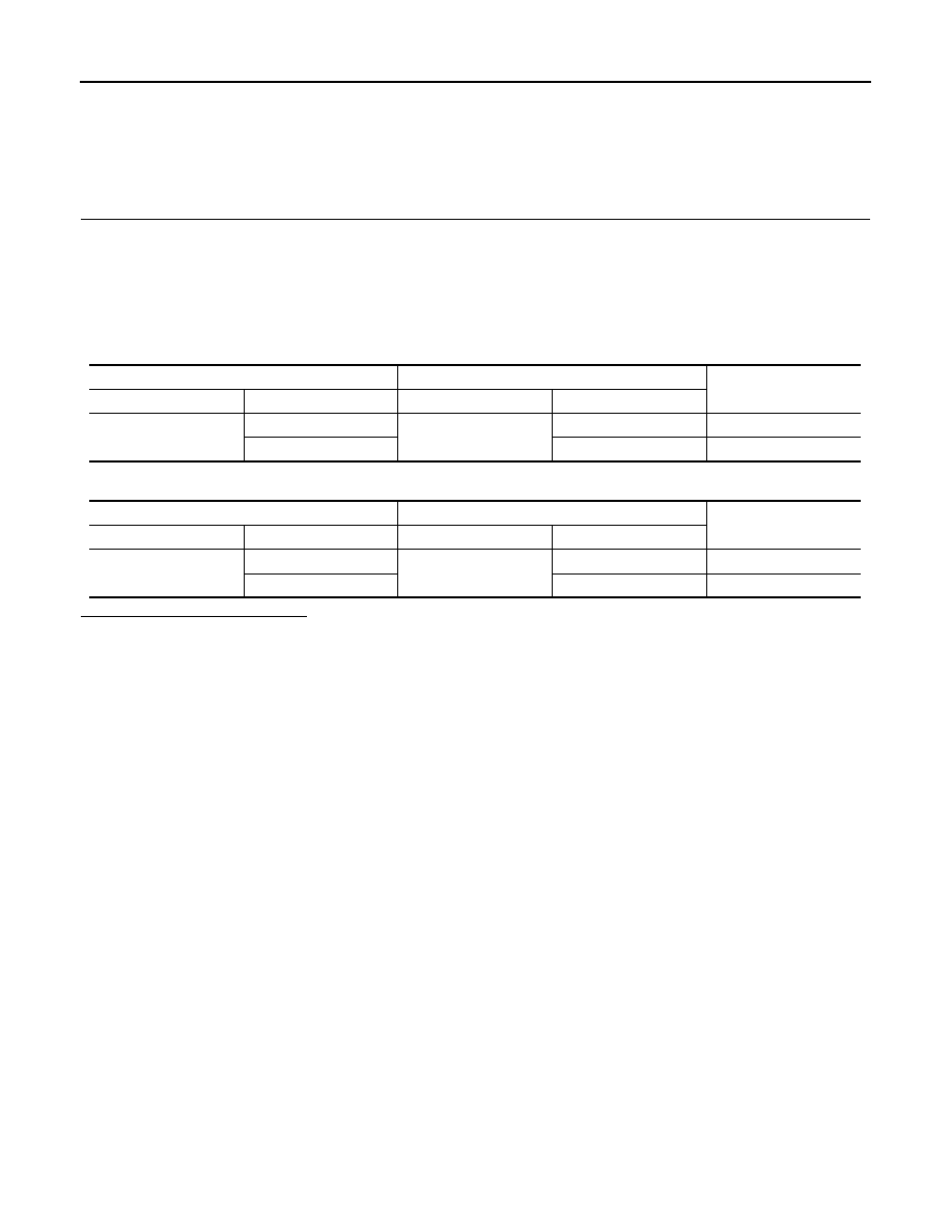
MAIN LINE BETWEEN AV AND DLC CIRCUIT
MAIN LINE BETWEEN AV AND DLC CIRCUIT
Diagnosis Procedure
INFOID:0000000003137638
INSPECTION PROCEDURE
1.
CHECK HARNESS CONTINUITY (OPEN CIRCUIT)
1.
Turn the ignition switch OFF.
2.
Disconnect the battery cable from the negative terminal.
3.
Disconnect the following harness connectors.
-
ECM
-
AV control unit
4.
Check the continuity between the AV control unit harness connector and the data link connector.
-
Models with NAVI
-
Models without NAVI
Is the inspection result normal?
YES (Present error)>>Check CAN system type decision again.
YES (Past error)>>Error was detected in the main line between the AV control unit and the data link connec-
tor.
NO
>> Repair the main line between the AV control unit and the data link connector.
AV control unit harness connector
Data link connector
Continuity
Connector No.
Terminal No.
Connector No.
Terminal No.
M87
52
M24
6
Existed
53
14
Existed
AV control unit harness connector
Data link connector
Continuity
Connector No.
Terminal No.
Connector No.
Terminal No.
M85
86
M24
6
Existed
87
14
Existed
LAN
MAIN LINE BETWEEN DLC AND TCM CIRCUIT
LAN-41
< COMPONENT DIAGNOSIS >
[CAN]
C
D
E
F
G
H
I
J
K
L
B
A
O
P
N
MAIN LINE BETWEEN DLC AND TCM CIRCUIT
Diagnosis Procedure
INFOID:0000000003514551
INSPECTION PROCEDURE
1.
CHECK HARNESS CONTINUITY (OPEN CIRCUIT)
1.
Turn the ignition switch OFF.
2.
Disconnect the battery cable from the negative terminal.
3.
Disconnect the following harness connectors.
-
ECM
-
Harness connectors M116 and F103
4.
Check the continuity between the data link connector and the harness connector.
Is the inspection result normal?
YES (Present error)>>Check CAN system type decision again.
YES (Past error)>>Error was detected in the main line between the data link connector and the TCM.
NO
>> Repair the main line between the data link connector and the harness connector M116.
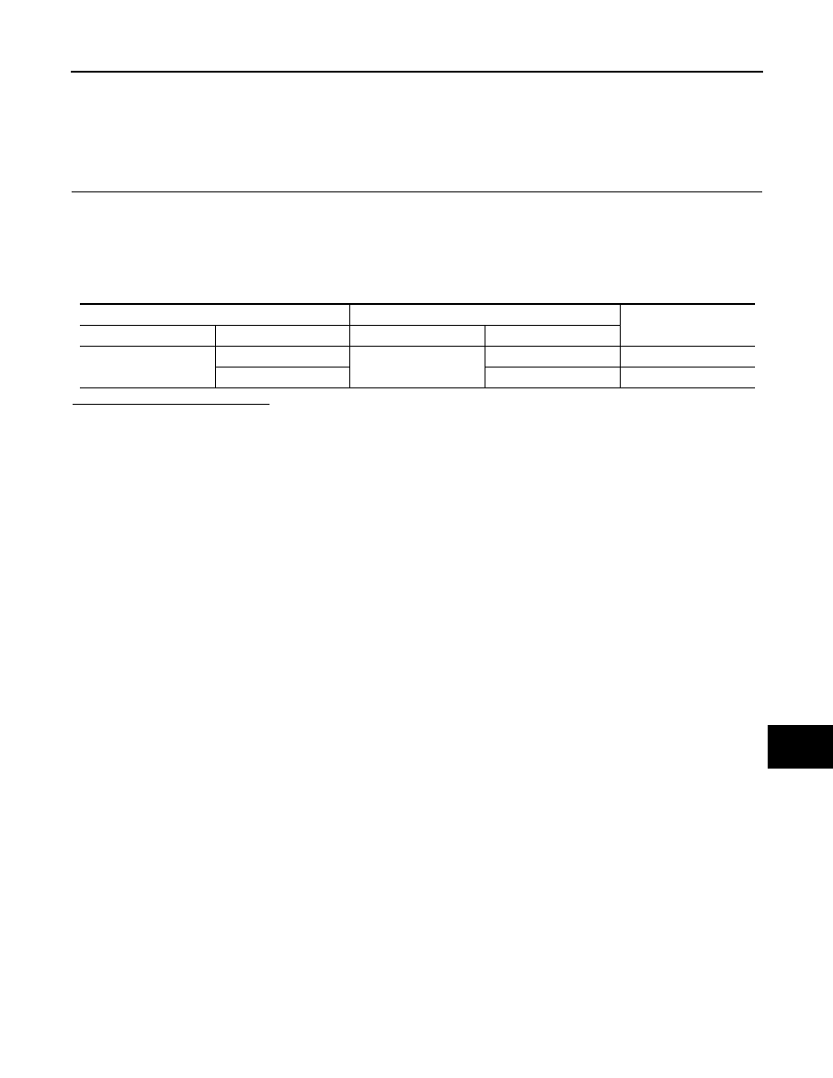
Data link connector
Harness connector
Continuity
Connector No.
Terminal No.
Connector No.
Terminal No.
M24
6
M116
44
Existed
14
43
Existed
LAN-42
< COMPONENT DIAGNOSIS >
[CAN]
MAIN LINE BETWEEN TCM AND ABS CIRCUIT
MAIN LINE BETWEEN TCM AND ABS CIRCUIT
Diagnosis Procedure
INFOID:0000000003137640
INSPECTION PROCEDURE
1.
CHECK CONNECTOR
1.
Turn the ignition switch OFF.
2.
Disconnect the battery cable from the negative terminal.
3.
Check the following terminals and connectors for damage, bend and loose connection (connector side
and harness side).
-
Harness connector M6
-
Harness connector E106
Is the inspection result normal?
YES
>> GO TO 2.
NO
>> Repair the terminal and connector.
2.
CHECK HARNESS CONTINUITY (OPEN CIRCUIT)
1.
Disconnect the following harness connectors.
-
Harness connectors F103 and M116
-
Harness connectors M6 and E106
2.
Check the continuity between the harness connectors.
Is the inspection result normal?
YES
>> GO TO 3.
NO
>> Repair the main line between the harness connectors M116 and M6.
3.
CHECK HARNESS CONTINUITY (OPEN CIRCUIT)
1.
Disconnect the connector of ABS actuator and electric unit (control unit).
2.
Check the continuity between the harness connector and the ABS actuator and electric unit (control unit)
harness connector.
Is the inspection result normal?
YES (Present error)>>Check CAN system type decision again.
YES (Past error)>>Error was detected in the main line between the TCM and the ABS actuator and electric
unit (control unit).
NO
>> Repair the main line between the harness connector E106 and the ABS actuator and electric unit
(control unit).
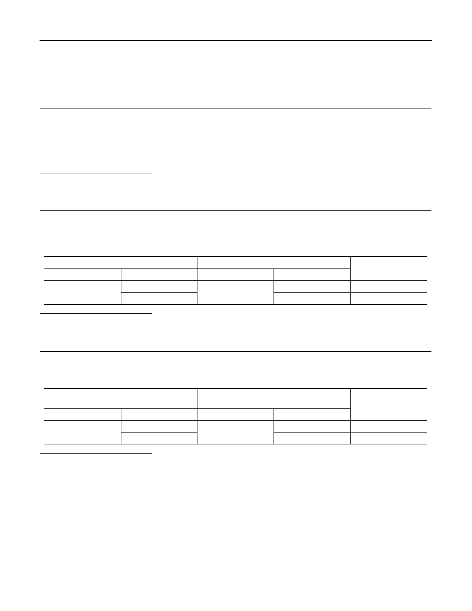
Harness connector
Harness connector
Continuity
Connector No.
Terminal No.
Connector No.
Terminal No.
M116
44
M6
82
Existed
43
81
Existed
Harness connector
ABS actuator and electric unit (control unit)
harness connector
Continuity
Connector No.
Terminal No.
Connector No.
Terminal No.
E106
82
E41
35
Existed
81
14
Existed
Нет комментариевНе стесняйтесь поделиться с нами вашим ценным мнением.
Текст