Infiniti EX35. Manual — part 581
EC-66
< FUNCTION DIAGNOSIS >
[VQ35HR]
COOLING FAN CONTROL
COOLING FAN CONTROL
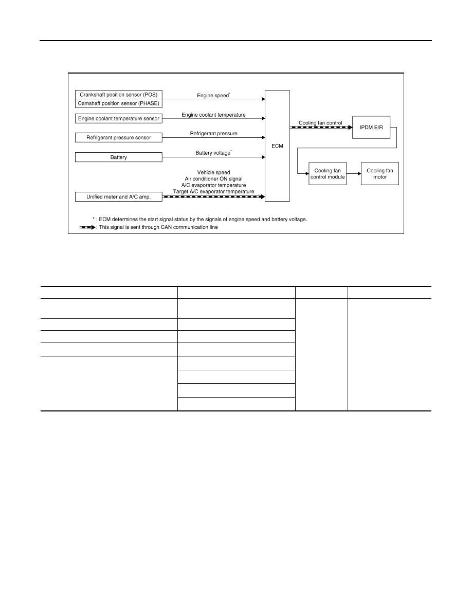
System Diagram
INFOID:0000000003133268
System Description
INFOID:0000000003133269
INPUT/OUTPUT SIGNAL CHART
*1: The ECM determines the start signal status by the signals of engine speed and battery voltage.
*2: This signal is sent to ECM through CAN communication line.
SYSTEM DESCRIPTION
ECM controls cooling fan speed corresponding to vehicle speed, engine coolant temperature, air conditioner
ON signal, refrigerant pressure, target A/C evaporator temperature and A/C evaporator temperature.
Cooling fan control signal is sent to IPDM E/R from ECM by CAN communication line. Then, IPDM E/R sends
ON/OFF pulse duty signal to cooling fan control module. Corresponding to this ON/OFF pulse duty signal,
cooling fan control module gives cooling fan motor operating voltage to cooling fan motors. Cooling fan speed
is controlled by duty cycle of cooling fan motor operating voltage sent from cooling fan control module.
JMBIA0075GB
Sensor
Input signal to ECM
ECM function
Actuator
Crankshaft position sensor (POS)
Camshaft position sensor (PHASE)
Engine speed*
1
Cooling fan
control
IPDM E/R
↓
Cooling fan control module
↓
Cooling fan motor
Engine coolant temperature sensor
Engine coolant temperature
Refrigerant pressure sensor
Refrigerant pressure
Battery
Battery voltage*
1
Unified meter and A/C amp.
Vehicle speed*
2
Air conditioner ON signal*
2
A/C evaporator temperature*
2
Target A/C evaporator temperature*
2
COOLING FAN CONTROL
EC-67
< FUNCTION DIAGNOSIS >
[VQ35HR]
C
D
E
F
G
H
I
J
K
L
M
A
EC
N
P
O
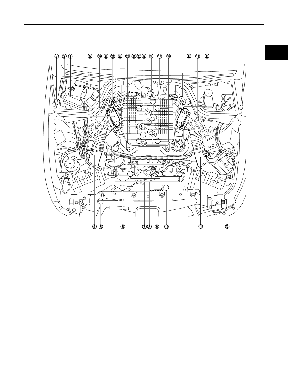
Component Parts Location
INFOID:0000000003738635
1.
Battery current sensor
2.
IPDM E/R
3.
Cooling fan relay
4.
Mass air flow sensor (with intake air
temperature sensor) (bank 1)
5.
Refrigerant pressure sensor
6.
Cooling fan motor-2
7.
Intake valve timing control solenoid
valve
8.
Exhaust valve timing control magnet
retarder
9.
Cooling fan control module
10. Cooling fan motor-1
11.
Mass air flow sensor (with intake air
temperature sensor) (bank 2)
12. ICC brake hold relay (ICC models)
13. Ignition coil (with power transistor)
and spark plug (bank 2)
14. Electric throttle control actuator
(bank 2)
15. A/F sensor 1 (bank 2)
16. Fuel injector (bank 2)
17. Camshaft position sensor (PHASE)
18. Engine coolant temperature sensor
19. Knock sensor
20. Exhaust valve timing control position
sensor
21. EVAP canister purge volume control
solenoid valve
22. Fuel injector (bank 1)
23. Ignition coil (with power transistor)
and spark plug (bank 1)
24. EVAP service port
25. A/F sensor 1 (bank 1)
26. Crankshaft position sensor (POS)
27. Electric throttle control actuator
(bank 1)
JMBIA0002ZZ
E
C
- 6
8
< FUNCTION DIAGNOSIS >
[VQ35HR]
COOLING FAN CONTROL
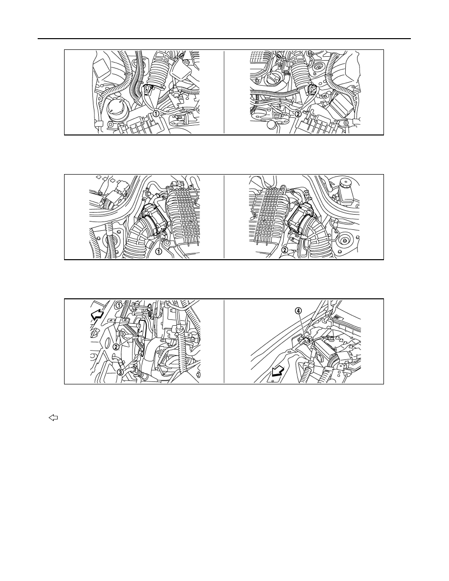
1.
Mass air flow sensor (with intake air
temperature sensor) (bank 1)
2.
Mass air flow sensor (with intake air
temperature sensor) (bank 2)
1.
Electric throttle control actuator
(bank 1)
2.
Electric throttle control actuator
(bank 2)
1.
Cooling fan motor-2
2.
Cooling fan control module
3.
Cooling fan motor-1
4.
Cooling fan relay
: Vehicle front
JMBIA0003ZZ
JMBIA0004ZZ
JMBIA0005ZZ
COOLING FAN CONTROL
EC-69
< FUNCTION DIAGNOSIS >
[VQ35HR]
C
D
E
F
G
H
I
J
K
L
M
A
EC
N
P
O
PBIB1907E
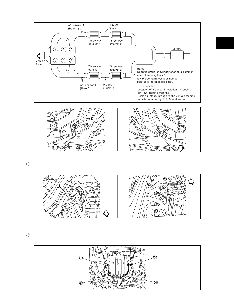
1.
A/F sensor 1 (bank 1)
2.
A/F sensor 1 (bank 2)
: Vehicle front
1.
A/F sensor 1 (bank 1) harness con-
nector
2.
A/F sensor 1 (bank 2) harness con-
nector
: Vehicle front
JMBIA0007ZZ
JMBIA0006ZZ
JMBIA0018ZZ
Нет комментариевНе стесняйтесь поделиться с нами вашим ценным мнением.
Текст