Infiniti EX35. Manual — part 567

EC-10
< BASIC INSPECTION >
[VQ35HR]
DIAGNOSIS AND REPAIR WORKFLOW
YES
>> GO TO 7.
NO
>> GO TO 9.
7.
PERFORM SPEC IN DATA MONITOR MODE
With CONSULT-III
Check that “MAS A/F SE-B1”, “MAS A/F SE-B2”, “B/FUEL SCHDL”, “A/F ALPHA-B1” and “A/F ALPHA-B2”
are within the SP value using CONSULT-III “SPEC” in “DATA MONITOR” mode. Refer to
Is the measurement value within the SP value?
YES
>> GO TO 9.
NO
>> GO TO 8.
8.
DETECT MALFUNCTIONING PART BY TROUBLE DIAGNOSIS - SPECIFICATION VALUE
Detect malfunctioning part according to
.
Is malfunctioning part detected?
YES
>> GO TO 11.
NO
>> GO TO 9.
9.
DETECT MALFUNCTIONING SYSTEM BY SYMPTOM TABLE
Detect malfunctioning system according to
based on the confirmed symptom in
step 4, and determine the trouble diagnosis order based on possible causes and symptom.
>> GO TO 10.
10.
DETECT MALFUNCTIONING PART BY DIAGNOSIS PROCEDURE
Inspect according to Diagnosis Procedure of the system.
NOTE:
The Diagnosis Procedure in EC section described based on open circuit inspection. A short circuit inspection
is also required for the circuit check in the Diagnosis Procedure. For details, refer to
.
Is malfunctioning part detected?
YES
>> GO TO 11.
NO
>> Monitor input data from related sensors or check voltage of related ECM terminals using CON-
SULT-III. Refer to
11.
REPAIR OR REPLACE THE MALFUNCTIONING PART
1.
Repair or replace the malfunctioning part.
2.
Reconnect parts or connectors disconnected during Diagnosis Procedure again after repair and replace-
ment.
3.
Check DTC. If DTC is displayed, erase it. Refer to
EC-100, "Diagnosis Description"
>> GO TO 12.
12.
FINAL CHECK
When DTC was detected in step 2, perform DTC CONFIRMATION PROCEDURE or Component Function
Check again, and then check that the malfunction have been repaired securely.
When symptom was described from the customer, refer to confirmed symptom in step 3 or 4, and check that
the symptom is not detected.
Is DTC detected and does symptom remain?
YES-1 >> DTC is detected: GO TO 10.
YES-2 >> Symptom remains: GO TO 6.
NO
>> Before returning the vehicle to the customer, erase unnecessary DTC in ECM and TCM (Trans-
mission Control Module) certainly. (Refer to
EC-100, "Diagnosis Description"
.) If the completion of
SRT is needed, drive vehicle under the specific driving pattern. Refer to
DIAGNOSIS AND REPAIR WORKFLOW
EC-11
< BASIC INSPECTION >
[VQ35HR]
C
D
E
F
G
H
I
J
K
L
M
A
EC
N
P
O
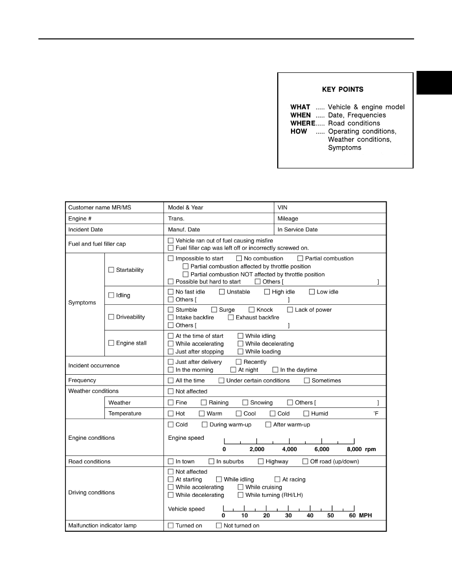
Diagnostic Work Sheet
INFOID:0000000003133227
DESCRIPTION
There are many operating conditions that lead to the malfunction of
engine components. A good grasp of such conditions can make trou-
bleshooting faster and more accurate.
In general, each customer feels differently about an incident. It is
important to fully understand the symptoms or conditions for a cus-
tomer complaint.
Utilize a diagnostic worksheet like the WORKSHEET SAMPLE
below in order to organize all the information for troubleshooting.
Some conditions may cause the MIL to come on steady or blink and
DTC to be detected. Examples:
• Vehicle ran out of fuel, which caused the engine to misfire.
• Fuel filler cap was left off or incorrectly screwed on, allowing fuel to
evaporate into the atmosphere.
WORKSHEET SAMPLE
SEF907L
MTBL0017
EC-12
< BASIC INSPECTION >
[VQ35HR]
INSPECTION AND ADJUSTMENT
INSPECTION AND ADJUSTMENT
BASIC INSPECTION
BASIC INSPECTION : Special Repair Requirement
INFOID:0000000003133228
1.
INSPECTION START
1.
Check service records for any recent repairs that may indicate a related malfunction, or a current need for
scheduled maintenance.
2.
Open engine hood and check the following:
-
Harness connectors for improper connections
-
Wiring harness for improper connections, pinches and cut
-
Vacuum hoses for splits, kinks and improper connections
-
Hoses and ducts for leaks
-
Air cleaner clogging
-
Gasket
3.
Confirm that electrical or mechanical loads are not applied.
-
Headlamp switch is OFF.
-
Air conditioner switch is OFF.
-
Rear window defogger switch is OFF.
-
Steering wheel is in the straight-ahead position, etc.
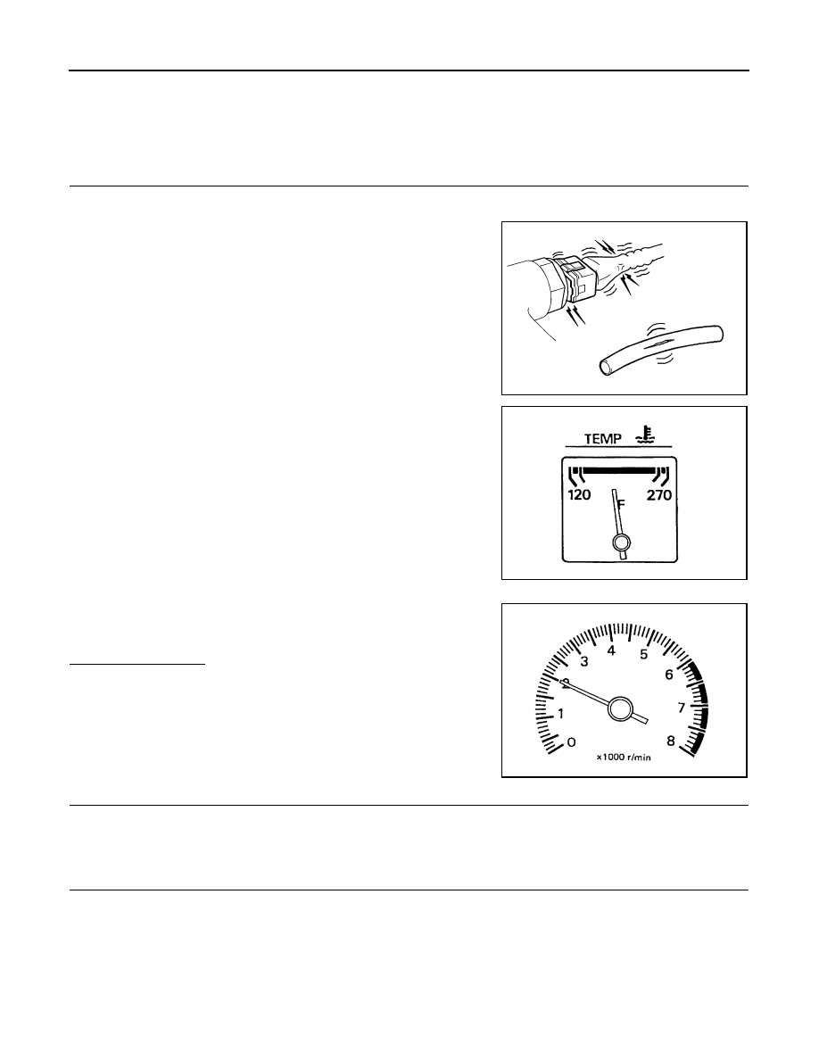
4.
Start engine and warm it up until engine coolant temperature
indicator points the middle of gauge.
Ensure engine stays below 1,000 rpm.
5.
Run engine at about 2,000 rpm for about 2 minutes under no
load.
6.
Check that no DTC is displayed with CONSULT-III or GST.
Is any DTC detected?
YES
>> GO TO 2.
NO
>> GO TO 3.
2.
REPAIR OR REPLACE
Repair or replace components as necessary according to corresponding Diagnosis Procedure.
>> GO TO 3
3.
CHECK TARGET IDLE SPEED
1.
Run engine at about 2,000 rpm for about 2 minutes under no load.
SEF983U
SEF976U
SEF977U
INSPECTION AND ADJUSTMENT
EC-13
< BASIC INSPECTION >
[VQ35HR]
C
D
E
F
G
H
I
J
K
L
M
A
EC
N
P
O
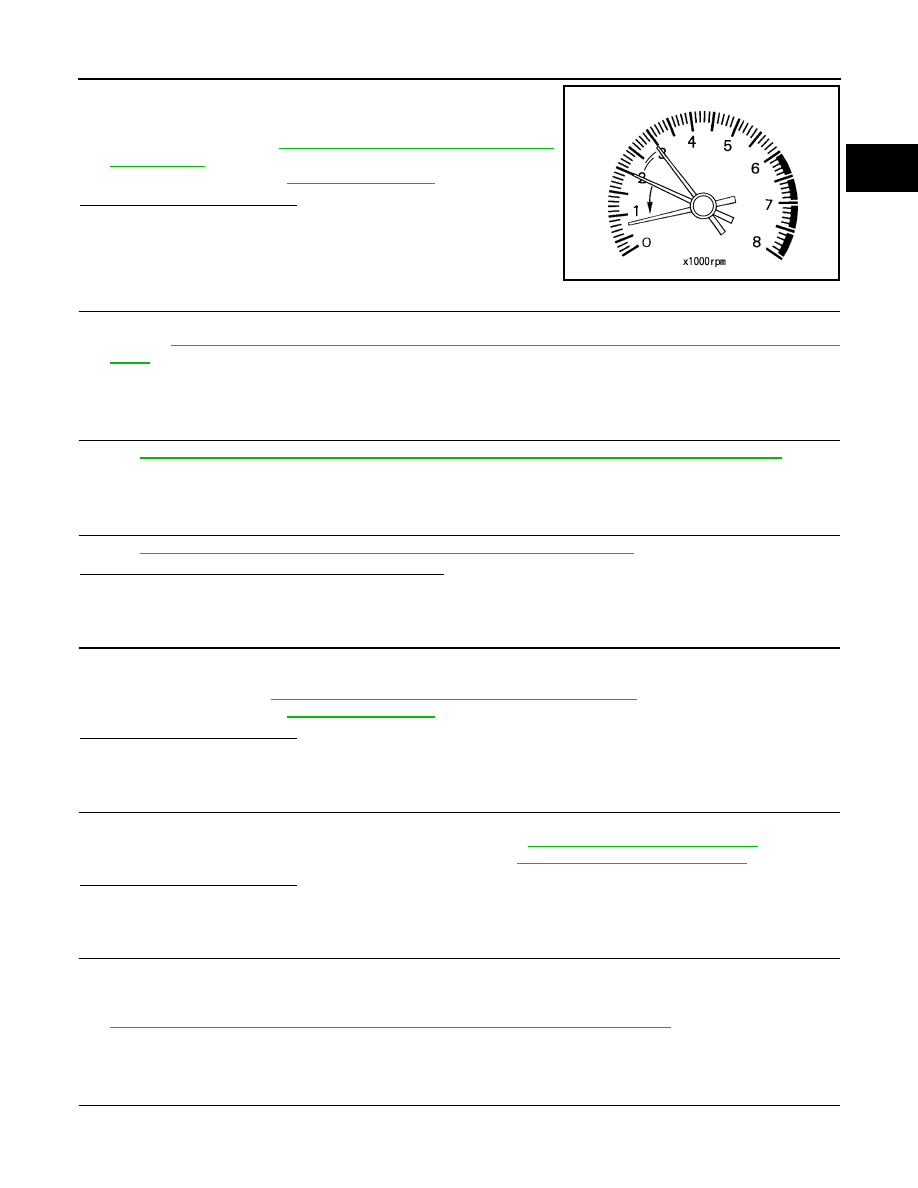
2.
Rev engine (2,000 to 3,000 rpm) two or three times under no
load, then run engine at idle speed for about 1 minute.
3.
Check idle speed.
For procedure, refer to
EC-16, "IDLE SPEED : Special Repair
.
For specification, refer to
Is the inspection result normal?
YES
>> GO TO 10.
NO
>> GO TO 4.
4.
PERFORM ACCELERATOR PEDAL RELEASED POSITION LEARNING
1.
Stop engine.
2.
Perform
EC-17, "ACCELERATOR PEDAL RELEASED POSITION LEARNING : Special Repair Require-
.
>> GO TO 5.
5.
PERFORM THROTTLE VALVE CLOSED POSITION LEARNING
Perform
EC-17, "THROTTLE VALVE CLOSED POSITION LEARNING : Special Repair Requirement"
>> GO TO 6.
6.
PERFORM IDLE AIR VOLUME LEARNING
Perform
EC-18, "IDLE AIR VOLUME LEARNING : Special Repair Requirement"
Is Idle Air Volume Learning carried out successfully?
YES
>> GO TO 7.
NO
>> Follow the instruction of Idle Air Volume Learning. Then GO TO 4.
7.
CHECK TARGET IDLE SPEED AGAIN
1.
Start engine and warm it up to normal operating temperature.
2.
Check idle speed.
For procedure, refer to
EC-16, "IDLE SPEED : Special Repair Requirement"
For specification, refer to
Is the inspection result normal?
YES
>> GO TO 10.
NO
>> GO TO 8.
8.
DETECT MALFUNCTIONING PART
Check the Following.
• Check camshaft position sensor (PHASE) and circuit. Refer to
EC-260, "Component Inspection"
.
• Check crankshaft position sensor (POS) and circuit. Refer to
EC-255, "Component Inspection"
Is the inspection result normal?
YES
>> GO TO 9.
NO
>> Repair or replace malfunctioning part. Then GO TO 4.
9.
CHECK ECM FUNCTION
1.
Substitute another known-good ECM to check ECM function. (ECM may be the cause of an incident, but
this is a rare case.)
2.
Perform initialization of IVIS (NATS) system and registration of all IVIS (NATS) ignition key IDs. Refer to
SEC-8, "ECM RE-COMMUNICATING FUNCTION : Special Repair Requirement"
.
>> GO TO 4.
10.
CHECK IGNITION TIMING
1.
Run engine at idle.
PBIA8513J
Нет комментариевНе стесняйтесь поделиться с нами вашим ценным мнением.
Текст