Infiniti EX35. Manual — part 1187

PWC-12
< FUNCTION DIAGNOSIS >
DIAGNOSIS SYSTEM (BCM)
The BCM records the following condition at the moment a particular DTC is detected.
• Vehicle Speed
• Odd Trip Meter
• Vehicle Condition (BCM detected condition)
IGN Counter
IGN counter indicates the number of times that ignition switch is turned ON after DTC is detected.
• The number is 0 when a malfunction is detected now.
• The number increases like 1
→
2
→
3...38
→
39 after returning to the normal condition whenever ignition
switch OFF
→
ON.
• The number is fixed to 39 until the self-diagnosis results are erased if it is over 39.
RETAINED PWR
RETAINED PWR : CONSULT-III Function (BCM - RETAINED PWR)
INFOID:0000000003573462
Data monitor
CONSULT screen terms
Description
SLEEP>LOCK
While turning BCM status from low power consumption mode to normal mode (Power supply
position is “LOCK”)
SLEEP>OFF
While turning BCM status from low power consumption mode to normal mode (Power supply
position is “OFF”.)
LOCK>ACC
While turning power supply position from “LOCK” to “ACC”
ACC>ON
While turning power supply position from “ACC” to “IGN”
RUN>ACC
While turning power supply position from “RUN” to “ACC” (Vehicle is stopping and selector
lever is except P position.)
CRANK>RUN
While turning power supply position from “CRANKING” to “RUN” (From cranking up the en-
gine to run it)
RUN>URGENT
While turning power supply position from “RUN“ to “ACC” (Emergency stop operation)
ACC>OFF
While turning power supply position from “ACC” to “OFF”
OFF>LOCK
While turning power supply position from “OFF” to “LOCK”
OFF>ACC
While turning power supply position from “OFF” to “ACC”
ON>CRANK
While turning power supply position from “IGN” to “CRANKING”
OFF>SLEEP
While turning BCM status from normal mode (Power supply position is “OFF”.) to low power
consumption mode
LOCK>SLEEP
While turning BCM status from normal mode (Power supply position is “LOCK”.) to low pow-
er consumption mode
LOCK
Power supply position is “LOCK” (Ignition switch OFF with steering is locked.)
OFF
Power supply position is “OFF” (Ignition switch OFF with steering is unlocked.)
ACC
Power supply position is “ACC” (Ignition switch ACC)
ON
Power supply position is “IGN” (Ignition switch ON with engine stopped)
ENGINE RUN
Power supply position is “RUN” (Ignition switch ON with engine running)
CRANKING
Power supply position is “CRANKING” (At engine cranking)
Monitor Item
Description
DOOR SW-DR
Indicates [ON/OFF] condition of driver side door switch.
DOOR SW-AS
Indicates [ON/OFF] condition of passenger side door switch.
POWER SUPPLY AND GROUND CIRCUIT
PWC-13
< COMPONENT DIAGNOSIS >
C
D
E
F
G
H
I
J
L
M
A
B
PWC
N
O
P
COMPONENT DIAGNOSIS
POWER SUPPLY AND GROUND CIRCUIT
BCM
BCM : Diagnosis Procedure
INFOID:0000000003573463
1.
CHECK FUSE AND FUSIBLE LINK
1.Turn ignition switch OFF.
2.Check that the following fuse and fusible link are not blown.
Is the fuse fusing?
YES
>> Replace the blown fuse or fusible link after repairing the affected circuit if a fuse or fusible link is
blown.
NO
>> GO TO 2.
2.
CHECK POWER SUPPLY CIRCUIT
1.
Disconnect BCM connectors.
2.
Check voltage between BCM harness connector and ground.
Is the inspection result normal?
YES
>> GO TO 3.
NO
>> Repair or replace harness or connector.
3.
CHECK GROUND CIRCUIT
Check continuity between BCM harness connector and ground.
Is the inspection result normal?
YES
>> INSPECTION END
NO
>> Repair or replace harness or connector.
POWER WINDOW MAIN SWITCH
POWER WINDOW MAIN SWITCH : Diagnosis Procedure
INFOID:0000000003573464
1.
CHECK POWER SUPPLY CIRCUIT 1
1.
Turn ignition OFF.
2.
Disconnect power window main switch connector.
3.
Turn ignition switch ON.
4.
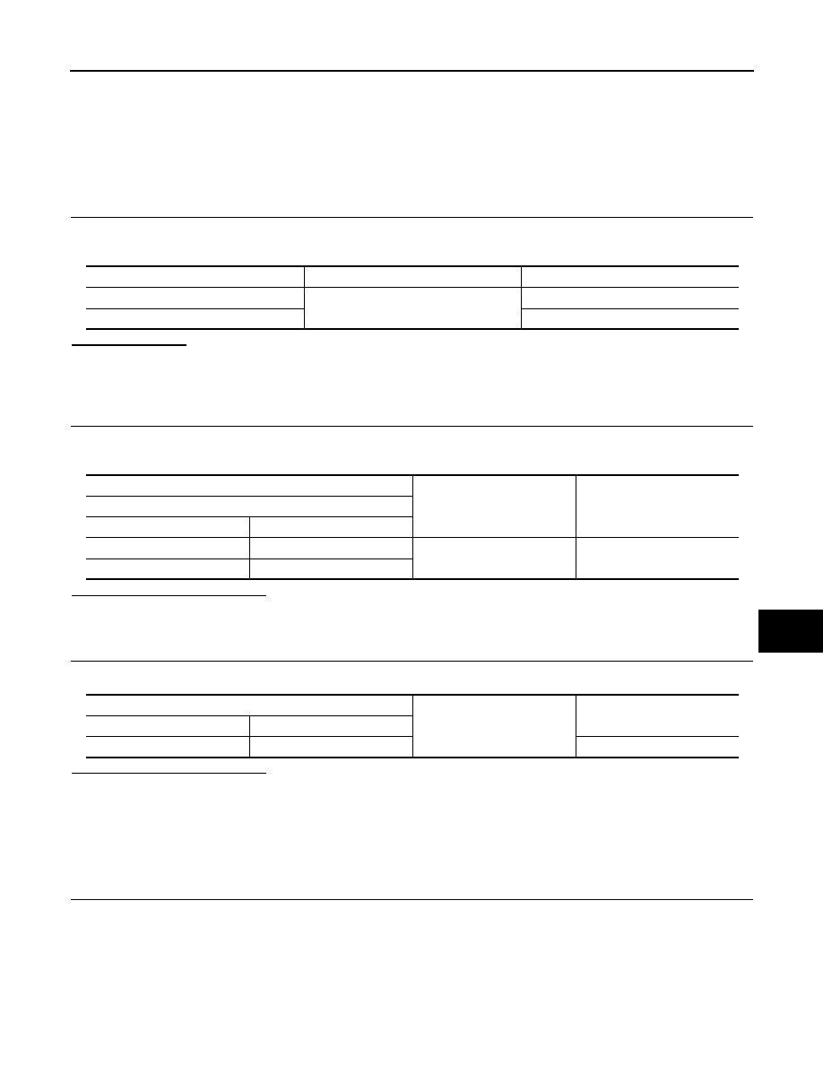
Check voltage between power window main switch harness connector and ground.
Terminal No.
Signal name
Fuse and fusible link No.
1
Battery power supply
K (40A)
11
10 (10A)
(+)
(
−
)
Voltage
(Approx.)
BCM
Connector
Terminal
M118
1
Ground
Battery voltage
M119
11
BCM
Ground
Continuity
Connector
Terminal
M119
13
Existed

PWC-14
< COMPONENT DIAGNOSIS >
POWER SUPPLY AND GROUND CIRCUIT
Is the inspection result normal?
YES
>> GO TO 2.
NO
>> GO TO 3.
2.
CHECK GROUND CIRCUIT
1.
Turn ignition switch OFF.
2.
Check continuity between power window main switch harness connector and ground.
Is the inspection result normal?
YES
>> INSPECTION END
NO
>> Repair or replace harness.
3.
CHECK POWER SUPPLY CIRCUIT 2
1.
Turn ignition switch OFF.
2.
Disconnect BCM connector.
3.
Check continuity between BCM harness connector and power window main switch harness connector.
4.
Check continuity between BCM harness connector and ground.
Is the inspection result normal?
YES
BCS-84, "Removal and Installation"
NO
>> Repair or replace harness.
FRONT POWER WINDOW SWITCH (PASSENGER SIDE)
FRONT POWER WINDOW SWITCH (PASSENGER SIDE) : Diagnosis Procedure
INFOID:0000000003573465
1.
CHECK POWER SUPPLY CIRCUIT 1
1.
Turn ignition switch OFF.
2.
Disconnect front power window switch (passenger side) connector.
3.
Turn ignition switch ON.
4.
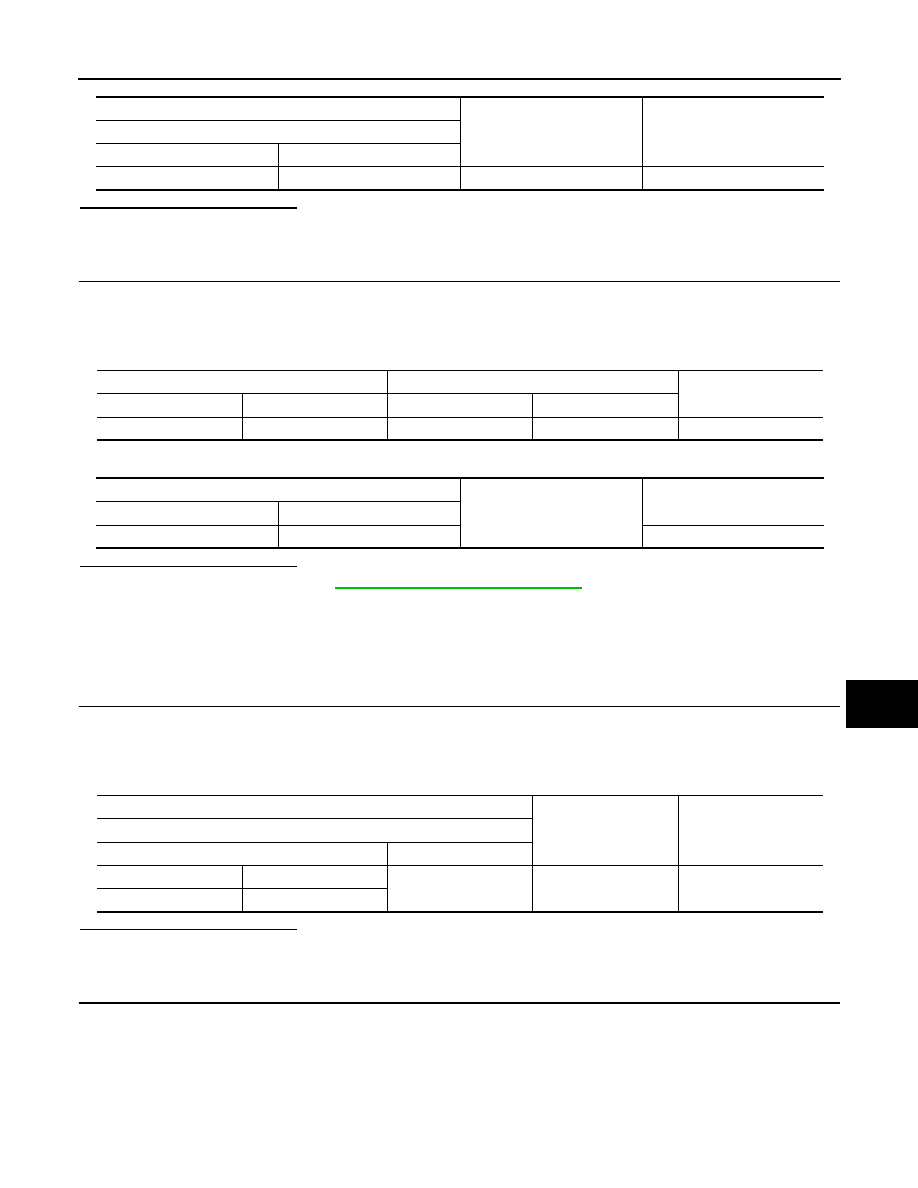
Check voltage between front power window switch (passenger side) harness connector and ground.
(+)
(–)
Voltage (V)
(Approx.)
Power window main switch
Connector
Terminal
D8
10
Ground
Battery voltage
D9
19
Power window main switch
Ground
Continuity
Connector
Terminal
D9
17
Existed
BCM
Power window main switch
Continuity
Connector
Terminal
Connector
Terminal
M118
2
D9
19
Existed
3
D8
10
BCM
Ground
Continuity
Connector
Terminal
M118
2
Not existed
3
POWER SUPPLY AND GROUND CIRCUIT
PWC-15
< COMPONENT DIAGNOSIS >
C
D
E
F
G
H
I
J
L
M
A
B
PWC
N
O
P
Is the inspection result normal?
YES
>> INSPECTION END.
NO
>> GO TO 2.
2.
CHECK POWER SUPPLY CIRCUIT 2
1.
Turn ignition switch OFF.
2.
Disconnect BCM connector.
3.
Check continuity between BCM harness connector and front power window switch (passenger side) har-
ness connector.
4.
Check continuity between BCM harness connector and ground.
Is the inspection result normal?
YES
>> Replace BCM. Refer to
BCS-84, "Removal and Installation"
NO
>> Repair or replace harness.
REAR POWER WINDOW SWITCH
REAR POWER WINDOW SWITCH : Diagnosis Procedure
INFOID:0000000003573466
1.
CHECK POWER SUPPLY CIRCUIT 1
1.
Turn ignition switch OFF.
2.
Disconnect rear power window switch connector.
3.
Turn ignition switch ON.
4.
Check voltage between rear power window switch harness connector and ground.
Is the inspection result normal?
YES
>> INSPECTION END.
NO
>> GO TO 2.
2.
CHECK POWER SUPPLY CIRCUIT 2
1.
Turn ignition switch OFF.
2.
Disconnect BCM connector.
3.
Check continuity between BCM harness connector and rear power window switch harness connector.
(+)
(–)
Voltage (V)
(Approx.)
Front power window switch (passenger side)
Connector
Terminal
D38
10
Ground
Battery voltage
BCM
Front power window switch (passenger side)
Continuity
Connector
Terminal
Connector
Terminal
M118
2
D38
10
Existed
BCM
Ground
Continuity
Connector
Terminal
M118
2
Not existed
(+)
(–)
Voltage (V)
(Approx.)
Rear power window switch
Connector
Terminal
LH
D54
1
Ground
Battery voltage
RH
D74
Нет комментариевНе стесняйтесь поделиться с нами вашим ценным мнением.
Текст