Infiniti EX35. Manual — part 687

EC-490
< ECU DIAGNOSIS >
[VQ35HR]
ECM
88
(LG)
—
Sensor ground
[Exhaust valve timing con-
trol position sensor (bank
1), Exhaust valve timing
control position sensor
(bank 2)]
—
—
—
91
(SB)
95
(G)
Battery current sensor
Input
[Engine is running]
• Battery: Fully charged*
2
• Idle speed
2.6 - 3.5 V
92
(P)
—
Sensor ground
[Camshaft position sensor
(PHASE) (bank 2)]
—
[Engine is running]
• Warm-up condition
• Idle speed
0 V
93
(P)
128
(B)
Power supply for ECM
(Back-up)
Input
[Ignition switch: OFF]
BATTERY VOLTAGE
(11 - 14 V)
94
(LG)
—
Sensor ground
[Mass air flow sensor (bank
2)]
—
—
—
95
(G)
—
Sensor ground
(Battery current sensor)
—
—
—
96
(B)
—
Sensor ground
[Camshaft position sensor
(PHASE) (bank 1), Power
steering pressure sensor]
—
—
—
97
(R)
100
(W)
Accelerator pedal position
sensor 1
Input
[Ignition switch: ON]
• Engine stopped
• Accelerator pedal: Fully released
0.5 - 1.0 V
[Ignition switch: ON]
• Engine stopped
• Accelerator pedal: Fully depressed
4.2 - 4.8 V
98
(P)
104
(GR)
Accelerator pedal position
sensor 2
Input
[Ignition switch: ON]
• Engine stopped
• Accelerator pedal: Fully released
0.25 - 0.50 V
[Ignition switch: ON]
• Engine stopped
• Accelerator pedal: Fully depressed
2.0 - 2.5 V
99
(L)
100
(W)
Sensor power supply
(Accelerator pedal position
sensor 1)
—
[Ignition switch: ON]
5 V
100
(W)
—
Sensor ground
(Accelerator pedal position
sensor 1)
—
—
—
Terminal No.
(Wire color)
Description
Condition
Value
(Approx.)
+
-–
Signal name
Input/
Output

ECM
EC-491
< ECU DIAGNOSIS >
[VQ35HR]
C
D
E
F
G
H
I
J
K
L
M
A
EC
N
P
O
101
(SB)
108
(Y)
ICC steering switch
(models with ICC system)
Input
[Ignition switch: ON]
• ICC steering switch: OFF
4.3 V
[Ignition switch: ON]
• MAIN switch: Pressed
0 V
[Ignition switch: ON]
• CANCEL switch: Pressed
1.3 V
[Ignition switch: ON]
• RESUME/ACCELERATE switch:
Pressed
3.7 V
[Ignition switch: ON]
• SET/COAST switch: Pressed
3 V
[Ignition switch: ON]
• DISTANCE switch: Pressed
2.2 V
101
(SB)
108
(Y)
ASCD steering switch
(models with ASCD sys-
tem)
Input
[Ignition switch: ON]
• ASCD steering switch: OFF
4 V
[Ignition switch: ON]
• MAIN switch: Pressed
0 V
[Ignition switch: ON]
• CANCEL switch: Pressed
1 V
[Ignition switch: ON]
• RESUME/ACCELERATE switch:
Pressed
3 V
[Ignition switch: ON]
• SET/COAST switch: Pressed
2 V
102
(LG)
112
(V)
EVAP control system pres-
sure sensor
Input
[Ignition switch: ON]
1.8 - 4.8 V
103
(G)
104
(GR)
Sensor power supply
(Accelerator pedal position
sensor 2)
—
[Ignition switch: ON]
5 V
104
(GR)
—
Sensor ground
(Accelerator pedal position
sensor 2)
—
—
—
105
(L)
116
(W)
Refrigerant pressure sen-
sor
Input
[Engine is running]
• Warm-up condition
• Both A/C switch and blower fan mo-
tor switch: ON (Compressor oper-
ates)
1.0 - 4.0 V
106
(W)
128
(B)
Fuel tank temperature sen-
sor
Input
[Engine is running]
0 - 4.8 V
Output voltage varies with fuel
tank temperature.
107
(BR)
112
(V)
Sensor power supply
(EVAP control system pres-
sure sensor)
—
[Ignition switch: ON]
5 V
108
(Y)
—
Sensor ground
(ASCD/ICC steering
switch)
—
—
—
109
(G)
128
(B)
PNP signal
Input
[Ignition switch: ON]
• Selector lever: P or N
BATTERY VOLTAGE
(11 - 14 V)
[Ignition switch: ON]
• Selector lever: Except above
0 V
Terminal No.
(Wire color)
Description
Condition
Value
(Approx.)
+
-–
Signal name
Input/
Output
EC-492
< ECU DIAGNOSIS >
[VQ35HR]
ECM
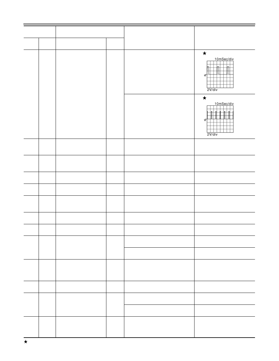
: Average voltage for pulse signal (Actual pulse signal can be confirmed by oscilloscope.)
110
(R)
128
(B)
Engine speed signal output
Output
[Engine is running]
• Warm-up condition
• Idle speed
NOTE:
The pulse cycle changes depending
on rpm at idle
1 V
[Engine is running]
• Engine speed is 2,000 rpm
1 V
111
(O)
116
(W)
Sensor power supply
(Refrigerant pressure sen-
sor)
—
[Ignition switch: ON]
5 V
112
(V)
—
Sensor ground
(EVAP control system pres-
sure sensor)
—
—
—
113
(P)
128
(B)
CAN communication line
Input/
Output
—
—
114
(L)
128
(B)
CAN communication line
Input/
Output
—
—
116
(W)
—
Sensor ground
(Refrigerant pressure sen-
sor)
—
—
—
117
(V)
—
Data link connector
Input/
Output
—
—
121
(LG)
128
(B)
EVAP canister vent control
valve
Output
[Ignition switch: ON]
BATTERY VOLTAGE
(11 - 14 V)
122
(P)
128
(B)
Stop lamp switch
Input
[Ignition switch: OFF]
• Brake pedal: Fully released
0 V
[Ignition switch: OFF]
• Brake pedal: Slightly depressed
BATTERY VOLTAGE
(11 - 14 V)
123
(B)
124
(B)
—
ECM ground
—
[Engine is running]
• Idle speed
Body ground
125
(R)
128
(B)
Power supply for ECM
Input
[Ignition switch: ON]
BATTERY VOLTAGE
(11 - 14 V)
126
(BR)
128
(B)
ICC brake switch (models
with ICC system)
ASCD brake switch (mod-
els with ASCD system)
Input
[Ignition switch: ON]
• Brake pedal: Slightly depressed
0 V
[Ignition switch: ON]
• Brake pedal: Fully released
BATTERY VOLTAGE
(11 - 14 V)
127
(B)
128
(B)
—
ECM ground
—
[Engine is running]
• Idle speed
Body ground
Terminal No.
(Wire color)
Description
Condition
Value
(Approx.)
+
-–
Signal name
Input/
Output
JMBIA0076GB
JMBIA0077GB
ECM
EC-493
< ECU DIAGNOSIS >
[VQ35HR]
C
D
E
F
G
H
I
J
K
L
M
A
EC
N
P
O
*1: This may vary depending on internal resistance of the tester.
**2: Before measuring the terminal voltage, confirm that the battery is fully charged. Refer to
.
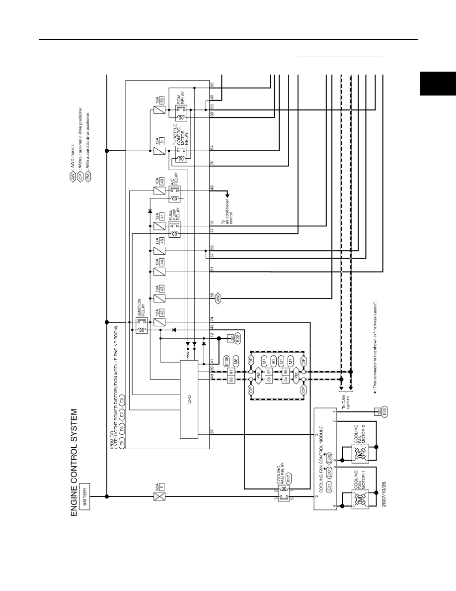
Wiring Diagram - ENGINE CONTROL SYSTEM -
INFOID:0000000003133668
JCBWM0470GB
Нет комментариевНе стесняйтесь поделиться с нами вашим ценным мнением.
Текст