Infiniti EX35. Manual — part 745

EXL-24
< FUNCTION DIAGNOSIS >
[XENON TYPE]
FRONT FOG LAMP SYSTEM
FRONT FOG LAMP SYSTEM
System Diagram
INFOID:0000000003135272
System Description
INFOID:0000000003135273
OUTLINE
Front fog lamp is controlled by combination switch reading function and front fog lamp control function of BCM,
and relay control function of IPDM E/R.
NOTE:
For Canada models, the front fog lamp is turned ON as the daytime running light. Refer to
for the detail.
FRONT FOG LAMP OPERATION
• BCM detects the combination switch condition by the combination switch reading function.
• BCM transmits the front fog light request signal to IPDM E/R and the combination meter (through the unified
meter and A/C amp.) with CAN communication according to the front fog lamp ON condition.
Front fog lamp ON condition
- Front fog lamp switch ON with the headlamp ON (except for the high beam ON)
• IPDM E/R turns the integrated front fog lamp relay ON, and turns the front fog lamp ON according to the
front fog light request signal.
• Combination meter turns the front fog lamp indicator lamp ON according to the front fog light request signal.
JPLIA0158GB

FRONT FOG LAMP SYSTEM
EXL-25
< FUNCTION DIAGNOSIS >
[XENON TYPE]
C
D
E
F
G
H
I
J
K
M
A
B
EXL
N
O
P
Component Parts Location
INFOID:0000000003135274
Component Description
INFOID:0000000003135275
1.
Front fog lamp
2.
Combination switch
3.
BCM
4.
IPDM E/R
5.
Front fog lamp indicator lamp
A.
Dash side lower (Passenger side)
B.
Engine room dash panel (RH)
C.
On the combination meter
JPLIA0945ZZ
Part
Description
BCM
• Judges each switch condition by the combination switch reading function.
• Judges the front fog lamp ON/OFF status according to the vehicle condition. Re-
quests the front fog lamp relay ON to IPDM E/R (with CAN communication).
IPDM E/R
Controls the integrated relay and supplies voltage to the load according to the request
from BCM (with CAN communication).
Combination switch
(Lighting & turn signal switch)
Refer to
.
Combination meter
(Front fog lamp indicator lamp)
Turns the front fog lamp indicator lamp ON according to the request from BCM [with
CAN communication (through the unified meter and A/C amp.)].
EXL-26
< FUNCTION DIAGNOSIS >
[XENON TYPE]
TURN SIGNAL AND HAZARD WARNING LAMP SYSTEM
TURN SIGNAL AND HAZARD WARNING LAMP SYSTEM
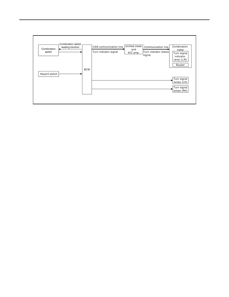
System Diagram
INFOID:0000000003135276
System Description
INFOID:0000000003135277
OUTLINE
Turn signal and the hazard warning lamp is controlled by combination switch reading function and the flasher
control function of BCM.
TURN SIGNAL LAMP OPERATION
• BCM detects the combination switch condition by the combination switch reading function.
• BCM supplies voltage to the right (left) turn signal lamp circuit when the ignition switch is turned ON and the
turn signal switch is in the right (left) position. BCM blinks the turn signal lamp.
HAZARD WARNING LAMP OPERATION
BCM supplies voltage to both turn signal lamp circuit when the hazard switch is turned ON. BCM blinks the
hazard warning lamp.
TURN SIGNAL INDICATOR LAMP AND TURN SIGNAL SOUND OPERATION
• BCM transmits the turn signal indicator lamp signal to the combination meter (through the unified meter and
A/C amp.) with CAN communication while the turn signal lamp and the hazard warning lamp operating.
• Combination meter outputs the turn signal sound with the integrated buzzer while blinking the turn signal
indicator lamp according to the turn signal indicator lamp signal.
HIGH FLASHER OPERATION (FAIL-SAFE)
• BCM detects the turn signal lamp circuit status from the current value.
• BCM increases the turn signal lamp blinking speed if the bulb or harness open is detected with the turn sig-
nal lamp operating.
NOTE:
The blinking speed is normal while operating the hazard warning lamp.
JPLIA0003GB
TURN SIGNAL AND HAZARD WARNING LAMP SYSTEM
EXL-27
< FUNCTION DIAGNOSIS >
[XENON TYPE]
C
D
E
F
G
H
I
J
K
M
A
B
EXL
N
O
P
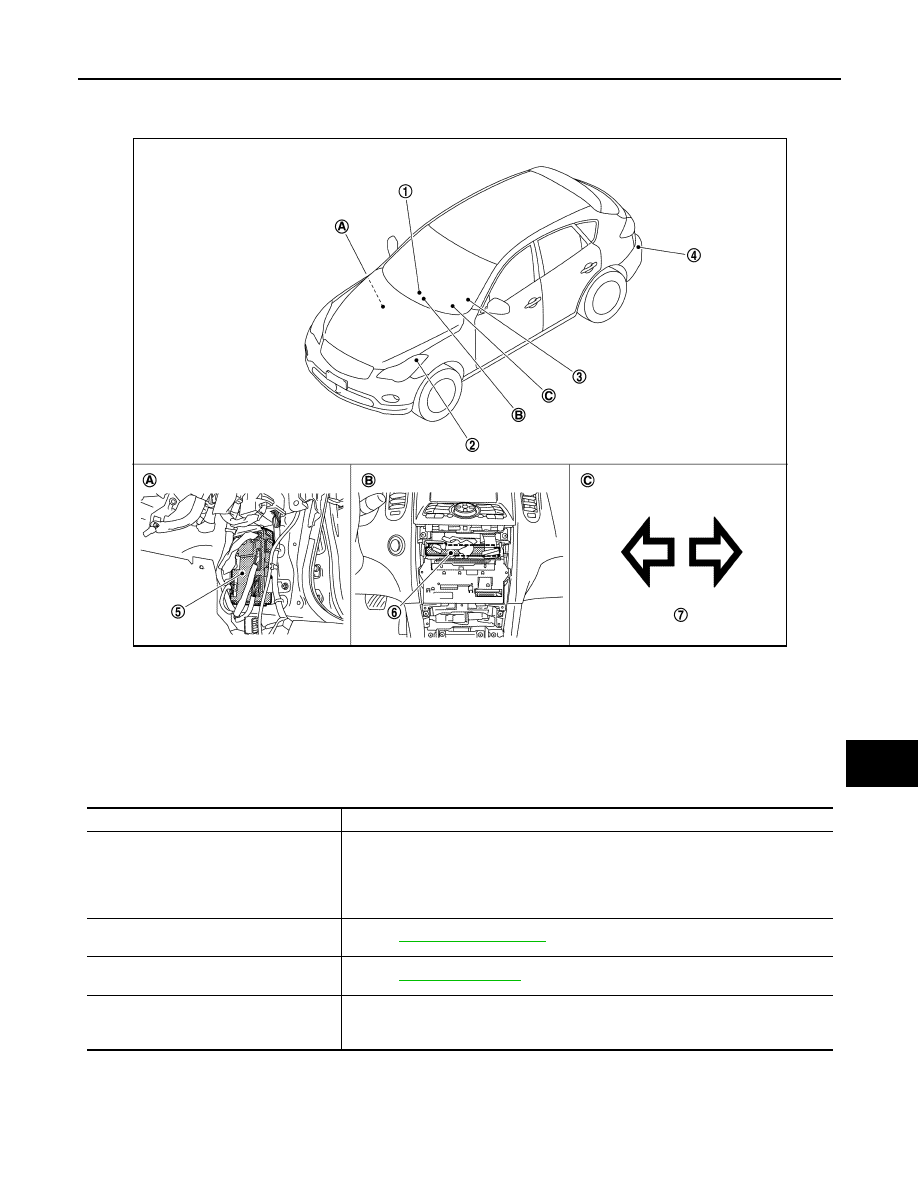
Component Parts Location
INFOID:0000000003135278
Component Description
INFOID:0000000003135279
1.
Hazard warning switch
2.
Front turn signal lamp
3.
Combination switch
4.
Rear turn signal lamp
5.
BCM
6.
Unified meter and A/C amp.
7.
Turn signal indicator lamp
A.
Dash side lower (Passenger side)
B.
Behind the cluster lid C
C.
On the combination meter
JPLIA0946ZZ
Part
Description
BCM
• Judges each switch condition by the combination switch reading function.
• Judges the blinks of the turn signal lamp and the hazard warning lamp from each
switch status. The applicable turn signal lamp blinks.
Requests the turn signal indicator lamp blink to the combination meter (with CAN
communication).
Combination switch
(Lighting & turn signal switch)
Refer to
.
Hazard switch
(Multifunction switch)
Refer to
Combination meter
(Turn signal indicator lamp & buzzer)
Blinks the turn signal indicator lamp and outputs the turn signal operating sound with
integrated buzzer according to the request from BCM [with CAN communication
(through unified meter and A/C amp.)].
Нет комментариевНе стесняйтесь поделиться с нами вашим ценным мнением.
Текст