Infiniti EX35. Manual — part 585
EC-82
< FUNCTION DIAGNOSIS >
[VQ35HR]
EVAPORATIVE EMISSION SYSTEM
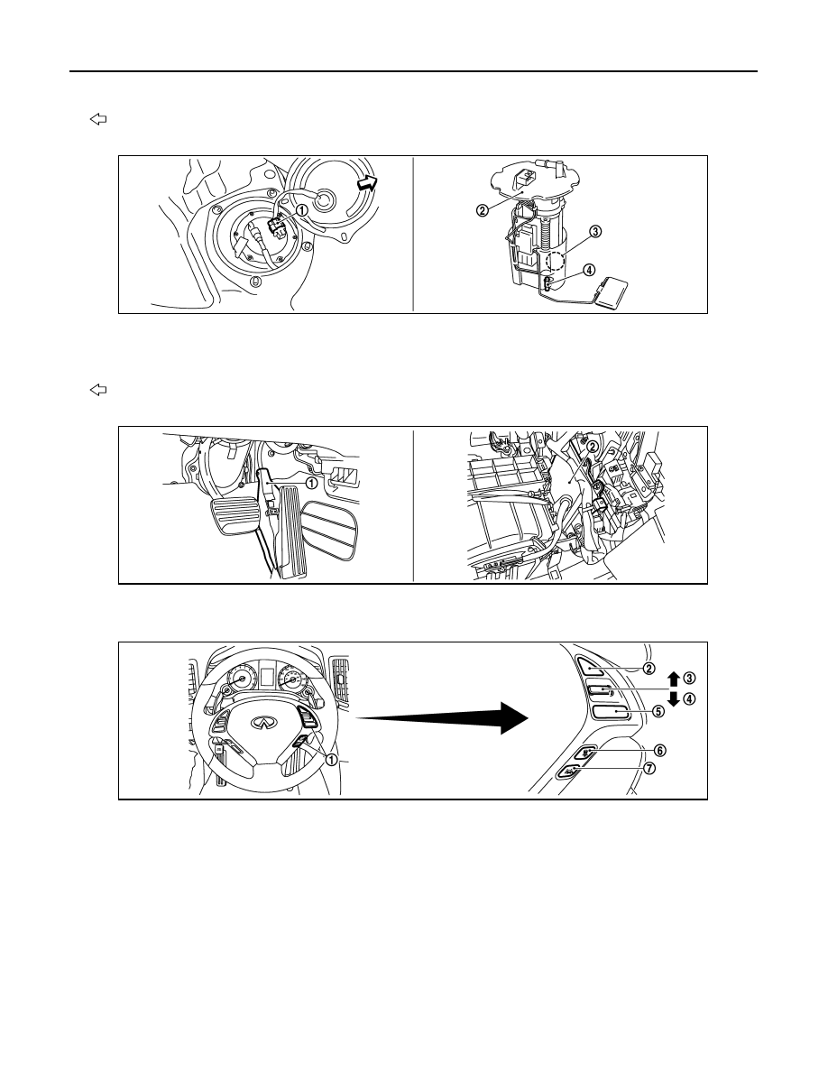
4.
EVAP canister vent control valve
5.
EVAP control system pressure sen-
sor
: Vehicle front
1.
Fuel level sensor unit and fuel pump
harness connector
2.
Fuel level sensor unit and fuel pump 3.
Fuel pressure regulator
4.
Fuel tank temperature sensor
: Vehicle front
1.
Accelerator pedal position sensor
2.
ECM
1.
ICC steering switch
2.
CANCEL switch
3.
RESUME/ACCELERATE switch
4.
SET/COAST switch
5.
MAIN switch
6.
DISTANCE switch
7.
LDP switch
JMBIA1182ZZ
JMBIA0015ZZ
JMBIA1308ZZ
EVAPORATIVE EMISSION SYSTEM
EC-83
< FUNCTION DIAGNOSIS >
[VQ35HR]
C
D
E
F
G
H
I
J
K
L
M
A
EC
N
P
O
Component Description
INFOID:0000000003133275
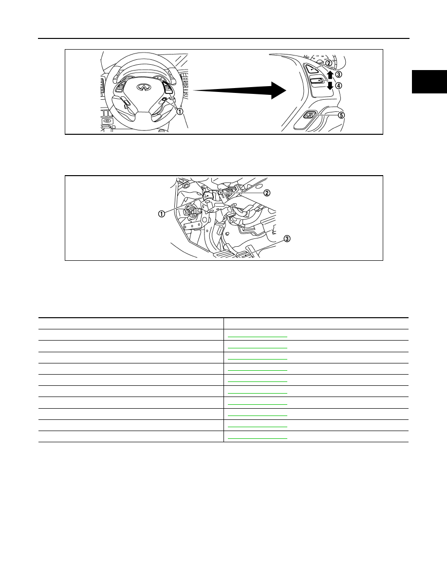
1.
ASCD steering switch
2.
CANCEL switch
3.
RESUME/ACCELERATE switch
4.
SET/COAST switch
5.
MAIN switch
1.
Stop lamp switch
2.
ASCD brake switch (ASCD models)
ICC brake switch (ICC models)
3.
Brake pedal
JMBIA0017ZZ
JMBIA0312ZZ
Component
Reference
A/F sensor 1
Accelerator pedal position sensor
Camshaft position sensor (PHASE)
Crankshaft position sensor (POS)
Engine coolant temperature sensor
EVAP canister purge volume control solenoid valve
EVAP control system pressure sensor
Fuel tank temperature sensor
Mass air flow sensor
Throttle position sensor
EC-84
< FUNCTION DIAGNOSIS >
[VQ35HR]
EXHAUST VALVE TIMING CONTROL
EXHAUST VALVE TIMING CONTROL
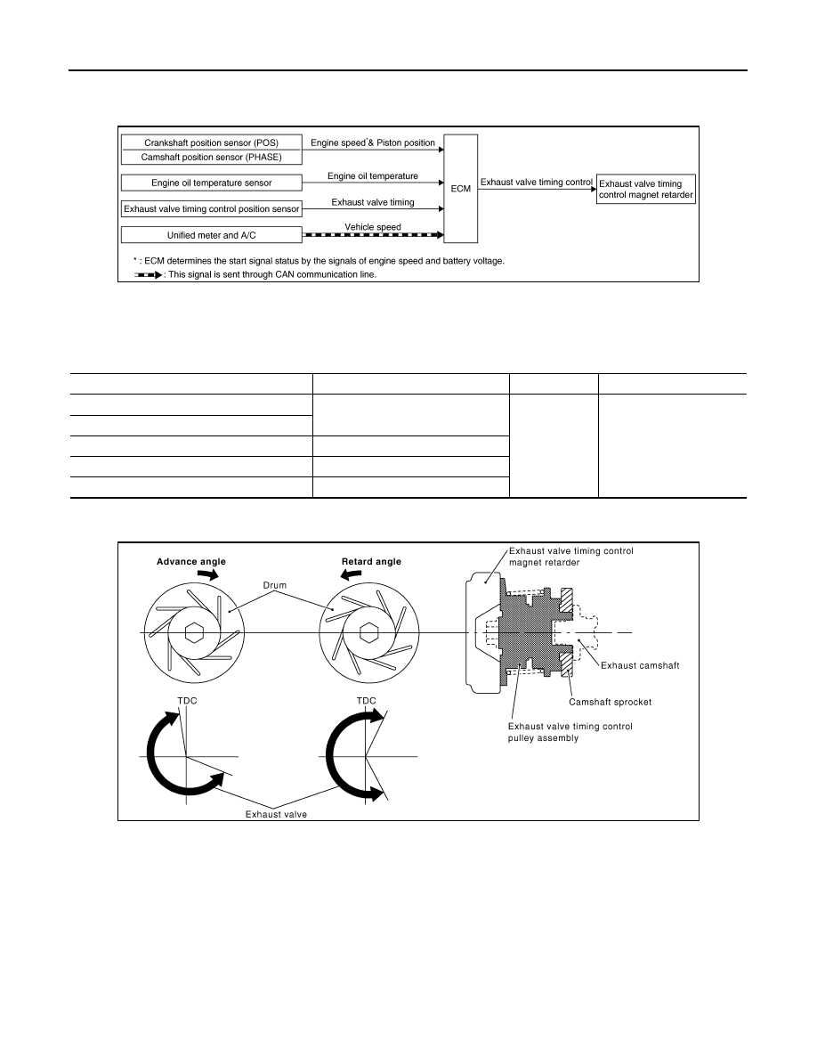
System Diagram
INFOID:0000000003133276
System Description
INFOID:0000000003133277
INPUT/OUTPUT SIGNAL CHART
*: This signal is sent to the ECM through CAN Communication line
SYSTEM DESCRIPTION
This mechanism magnetically controls cam phases continuously with the fixed operating angle of the exhaust
valve.
The ECM receives signals such as crankshaft position, camshaft position, engine speed, and engine oil tem-
perature. Then, the ECM sends ON/OFF pulse duty signals to the exhaust valve timing control magnet
retarder depending on driving status. This makes it possible to control the shut/open timing of the exhaust
valve to increase engine torque and output in a range of high engine speed.
JMBIA1318GB
Sensor
Input signal to ECM
ECM function
Actuator
Crankshaft position sensor (POS)
Engine speed and piston position
Exhaust valve
timing control
Exhaust valve timing con-
trol magnet retarder
Camshaft position sensor (PHASE)
Engine oil temperature sensor
Engine oil temperature
Exhaust valve timing control position sensor
Exhaust valve timing signal
Unified meter and A/C amp.
Vehicle speed*
PBIB2765E
EXHAUST VALVE TIMING CONTROL
EC-85
< FUNCTION DIAGNOSIS >
[VQ35HR]
C
D
E
F
G
H
I
J
K
L
M
A
EC
N
P
O
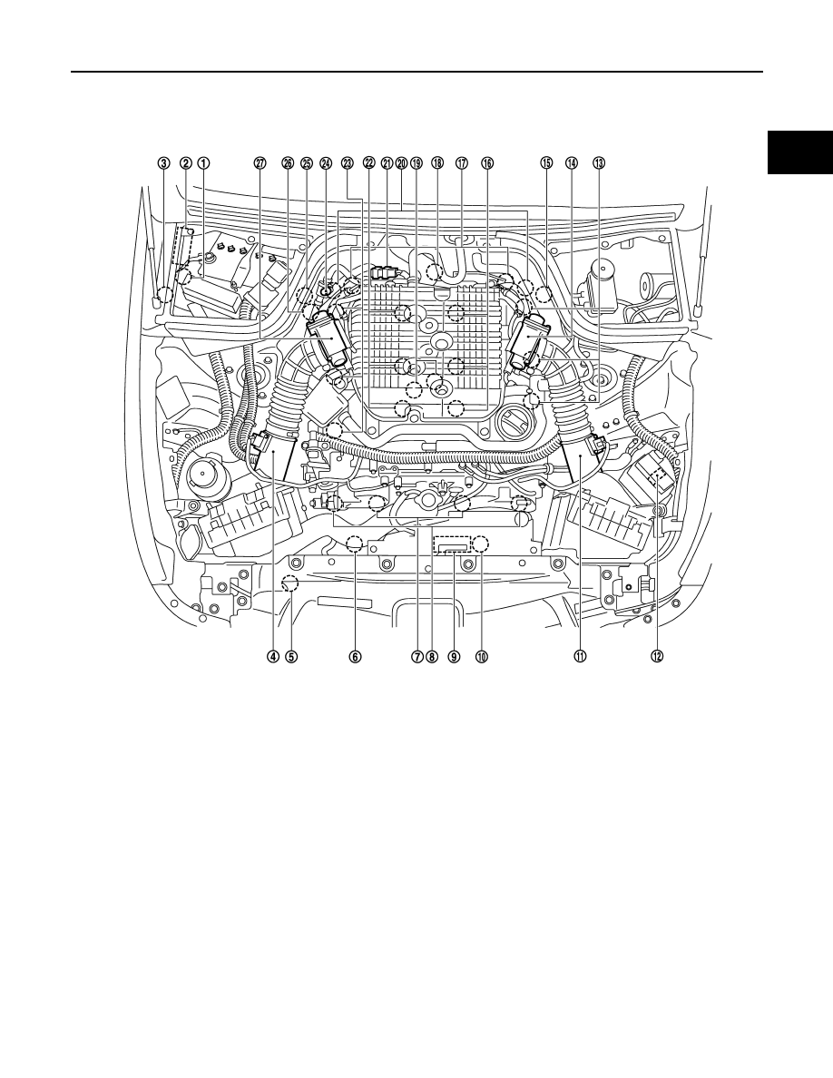
Component Parts Location
INFOID:0000000003738637
1.
Battery current sensor
2.
IPDM E/R
3.
Cooling fan relay
4.
Mass air flow sensor (with intake air
temperature sensor) (bank 1)
5.
Refrigerant pressure sensor
6.
Cooling fan motor-2
7.
Intake valve timing control solenoid
valve
8.
Exhaust valve timing control magnet
retarder
9.
Cooling fan control module
10. Cooling fan motor-1
11.
Mass air flow sensor (with intake air
temperature sensor) (bank 2)
12. ICC brake hold relay (ICC models)
13. Ignition coil (with power transistor)
and spark plug (bank 2)
14. Electric throttle control actuator
(bank 2)
15. A/F sensor 1 (bank 2)
16. Fuel injector (bank 2)
17. Camshaft position sensor (PHASE)
18. Engine coolant temperature sensor
19. Knock sensor
20. Exhaust valve timing control position
sensor
21. EVAP canister purge volume control
solenoid valve
22. Fuel injector (bank 1)
23. Ignition coil (with power transistor)
and spark plug (bank 1)
24. EVAP service port
25. A/F sensor 1 (bank 1)
26. Crankshaft position sensor (POS)
27. Electric throttle control actuator
(bank 1)
JMBIA0002ZZ
Нет комментариевНе стесняйтесь поделиться с нами вашим ценным мнением.
Текст