Infiniti EX35. Manual — part 1269
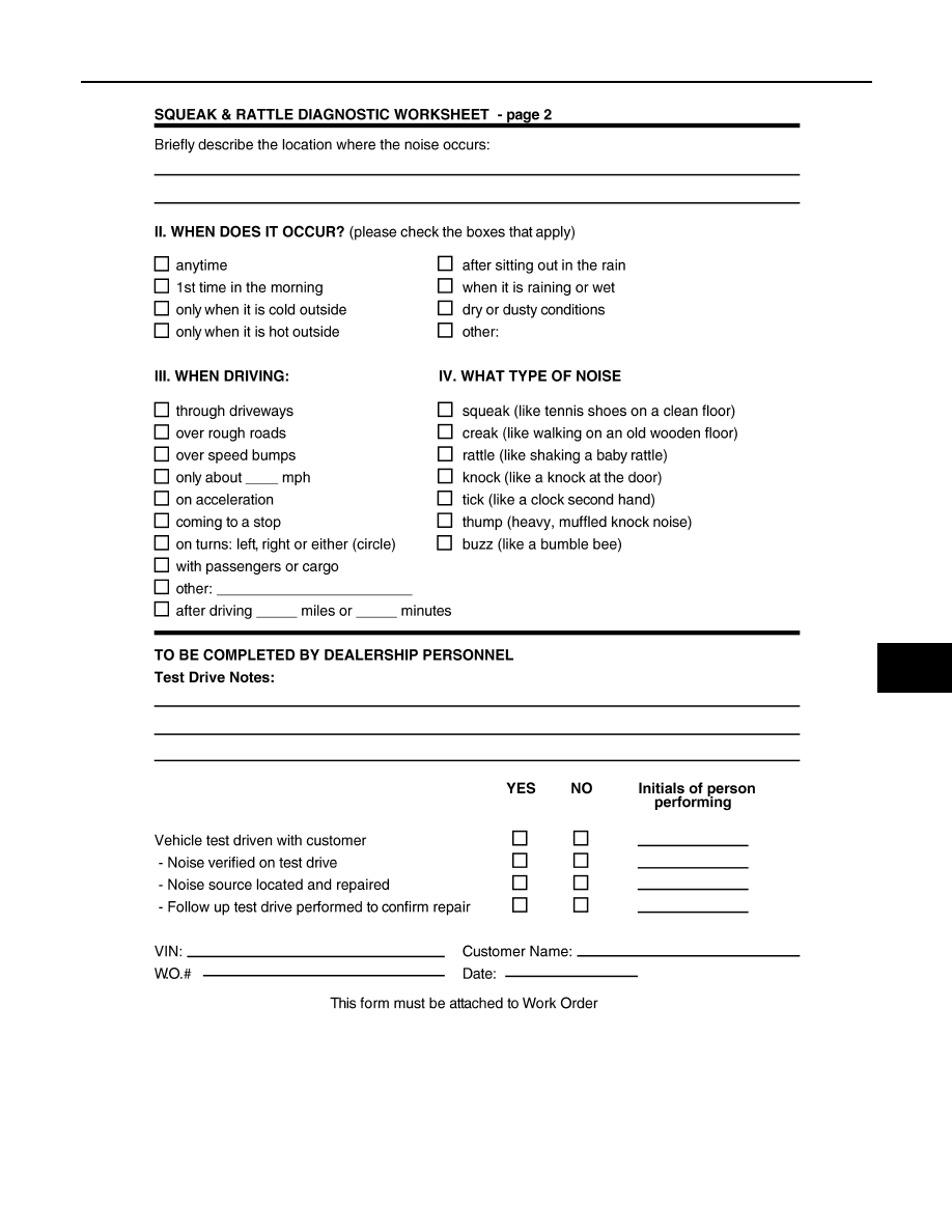
SQUEAK AND RATTLE TROUBLE DIAGNOSES
SE-83
< SYMPTOM DIAGNOSIS >
C
D
E
F
G
H
I
K
L
M
A
B
SE
N
O
P
PIIB8742E
SE-84
< PRECAUTION >
PRECAUTIONS
PRECAUTION
PRECAUTIONS
Precaution for Supplemental Restraint System (SRS) "AIR BAG" and "SEAT BELT
PRE-TENSIONER"
INFOID:0000000003736025
The Supplemental Restraint System such as “AIR BAG” and “SEAT BELT PRE-TENSIONER”, used along
with a front seat belt, helps to reduce the risk or severity of injury to the driver and front passenger for certain
types of collision. This system includes seat belt switch inputs and dual stage front air bag modules. The SRS
system uses the seat belt switches to determine the front air bag deployment, and may only deploy one front
air bag, depending on the severity of a collision and whether the front occupants are belted or unbelted.
Information necessary to service the system safely is included in the “SRS AIRBAG” and “SEAT BELT” of this
Service Manual.
WARNING:
• To avoid rendering the SRS inoperative, which could increase the risk of personal injury or death in
the event of a collision which would result in air bag inflation, all maintenance must be performed by
an authorized NISSAN/INFINITI dealer.
• Improper maintenance, including incorrect removal and installation of the SRS, can lead to personal
injury caused by unintentional activation of the system. For removal of Spiral Cable and Air Bag
Module, see the “SRS AIRBAG”.
• Do not use electrical test equipment on any circuit related to the SRS unless instructed to in this
Service Manual. SRS wiring harnesses can be identified by yellow and/or orange harnesses or har-
ness connectors.
Precaution Necessary for Steering Wheel Rotation after Battery Disconnect
INFOID:0000000003736071
NOTE:
• Before removing and installing any control units, first turn the push-button ignition switch to the LOCK posi-
tion, then disconnect both battery cables.
• After finishing work, confirm that all control unit connectors are connected properly, then re-connect both
battery cables.
• Always use CONSULT-III to perform self-diagnosis as a part of each function inspection after finishing work.
If a DTC is detected, perform trouble diagnosis according to self-diagnosis results.
This vehicle is equipped with a push-button ignition switch and a steering lock unit.
If the battery is disconnected or discharged, the steering wheel will lock and cannot be turned.
If turning the steering wheel is required with the battery disconnected or discharged, follow the procedure
below before starting the repair operation.
OPERATION PROCEDURE
1.
Connect both battery cables.
NOTE:
Supply power using jumper cables if battery is discharged.
2.
Turn the push-button ignition switch to ACC position.
(At this time, the steering lock will be released.)
3.
Disconnect both battery cables. The steering lock will remain released with both battery cables discon-
nected and the steering wheel can be turned.
4.
Perform the necessary repair operation.
5.
When the repair work is completed, re-connect both battery cables. With the brake pedal released, turn
the push-button ignition switch from ACC position to ON position, then to LOCK position. (The steering
wheel will lock when the push-button ignition switch is turned to LOCK position.)
6.
Perform self-diagnosis check of all control units using CONSULT-III.
Service Notice
INFOID:0000000003508323
• When removing or installing various parts, place a cloth or padding onto the vehicle body to prevent
scratches.
• Handle trim, molding, instruments, grille, etc. carefully during removing or installing. Be careful not to oil or
damage them.
PRECAUTIONS
SE-85
< PRECAUTION >
C
D
E
F
G
H
I
K
L
M
A
B
SE
N
O
P
• Apply sealing compound where necessary when installing parts.
• When applying sealing compound, be careful that the sealing compound does not protrude from parts.
• When replacing any metal parts (for example body outer panel, members, etc.), be sure to take rust preven-
tion measures.
Precaution for Work
INFOID:0000000003508324
• When removing or disassembling each component, be careful not to damage or deform it. If a component
may be subject to interference, be sure to protect it with a shop cloth.
• When removing (disengaging) components with a screwdriver or similar tool, be sure to wrap the component
with a shop cloth or vinyl tape to protect it.
• Protect the removed parts with a shop cloth and keep them.
• Replace a deformed or damaged clip.
• If a part is specified as a non-reusable part, always replace it with new one.
• Be sure to tighten bolts and nuts securely to the specified torque.
• After re-installation is completed, be sure to check that each part works normally.
• Follow the steps below to clean components.
- Water soluble foul: Dip a soft cloth into lukewarm water, and wring the water out of the cloth to wipe the
fouled area.
Then rub with a soft and dry cloth.
- Oily foul: Dip a soft cloth into lukewarm water with mild detergent (concentration: within 2 to 3%), and wipe
the fouled area.
Then dip a cloth into fresh water, and wring the water out of the cloth to wipe the detergent off. Then rub with
a soft and dry cloth.
• Do not use organic solvent such as thinner, benzene, alcohol, and gasoline.
• For genuine leather seats, use a genuine leather seat cleaner.
SE-86
< PREPARATION >
PREPARATION
PREPARATION
PREPARATION
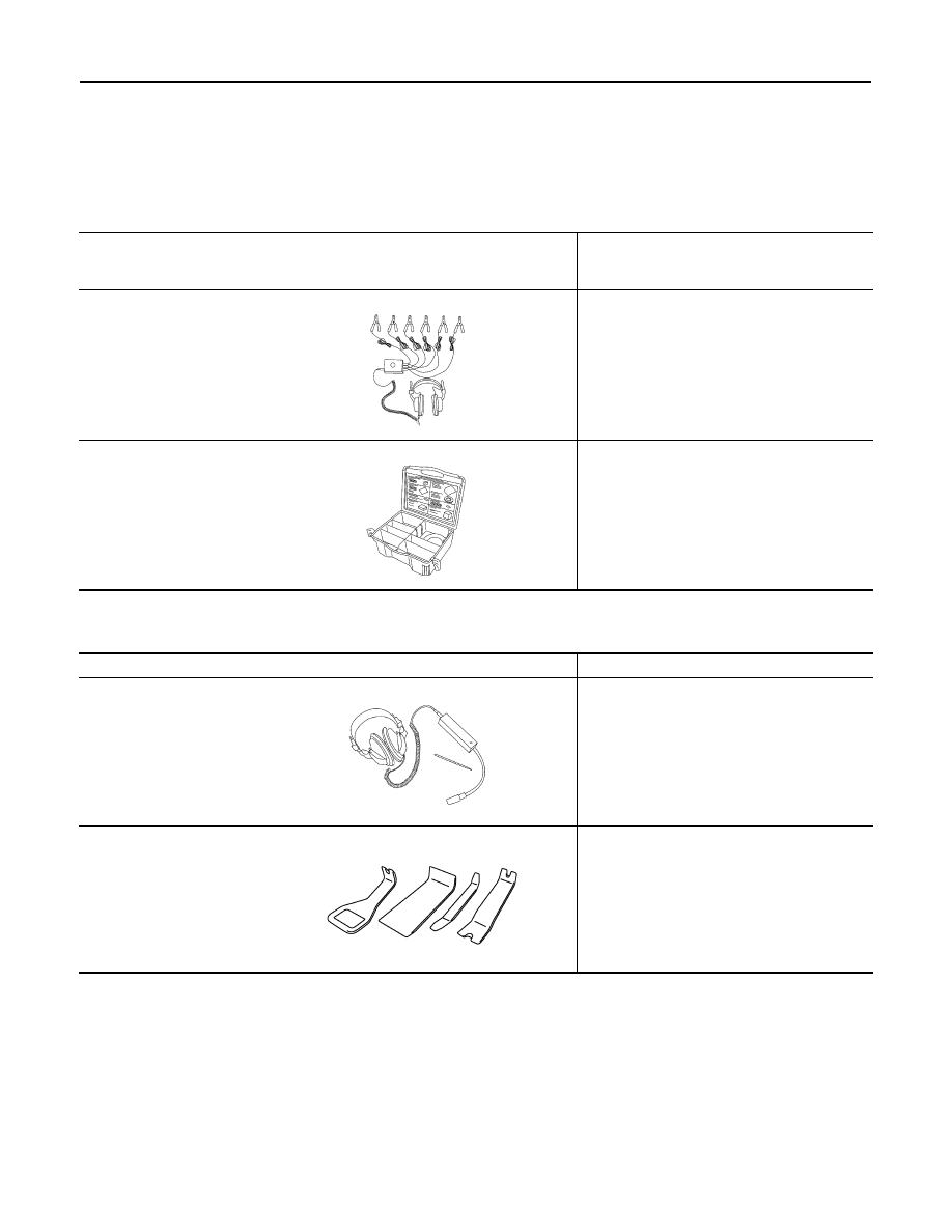
Special Service Tool
INFOID:0000000003508325
The actual shapes of Kent-Moore tools may differ from those of special service tools illustrated here.
Commercial Service Tool
INFOID:0000000003508326
Tool number
(Kent-Moore No.)
Tool name
Description
(J39570)
Chassis ear
Locating the noise
(J43980)
NISSAN Squeak and Rattle
Kit
Repairing the cause of noise
SIIA0993E
SIIA0994E
Tool name
Description
Engine ear
Locating the noise
Remover tool
Remove the clips, pawls and metal clips
SIIA0995E
PIIB7923J
Нет комментариевНе стесняйтесь поделиться с нами вашим ценным мнением.
Текст